FANUC Series 0i-MODEL F Plus. CONNECTION MANUAL (FUNCTION) - page 383
 

  Index      Manuals     FANUC Series 0i-MODEL F Plus. CONNECTION MANUAL (FUNCTION) B-64693EN-1/01


Search            copyright infringement  


Content      ..     381      382      383      384     ..


FANUC Series 0i-MODEL F Plus. CONNECTION MANUAL (FUNCTION) - page 383


B-64693EN-1/01


APPENDIX


F. 0i-F PLUS START-UP PROCEDURE


- 3021 - 


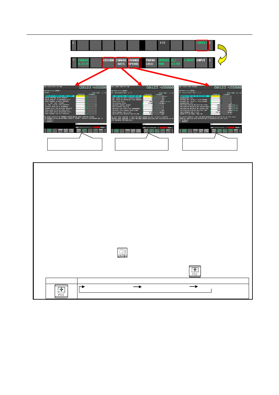
Screen of setting item   

"Common" 

Screen of setting item   

"Axis" 

Screen of setting item   

"Spindle" 


Fig. F.2 (c) Setting item "Common", "Axis", "Spindle" 


NOTE 

1.  The parameter value on the FCS screen differs from the value displayed on the 

parameter screen and is displayed in general unit. 
Example 1) 
Display contents of parameter No. 1826 when the metric system machine, the 
detection unit 0.001 (IS-B, CMR = 1) 
    Parameter screen 

100 [detection unit] 

    FCS screen 

0.100 [mm] 

Example 2) 
Display contents of parameter No. 2092 
    Parameter screen 

9800 [0.01%] 

    FCS screen 

98.00 [%] 

2.  When the parameter FCS is 0 (when "ADJUST"), the FCS screen is added to the 

tab stop of the function key 


. Tab stop means that predetermined screens 

are displayed in order when the function key is repeatedly pressed. 

Example)    The screen displayed when the function key 


  is pressed. 

Function key 

Displayed screen and order 


  Absolute position screen


  Relative position screen


  Overall position display 


Step 3 : Selection of machine size 

By pressing the soft key [CHANGE M.SIZE], the machine size can selected from the 3 patterns. Select 
the appropriate one (or closer one). 
0

i

-MF Plus : Spindle taper size [BT30 / BT40 / BT50] 

0

i

-TF Plus : Auto lathe and chuck size [AUTO LATHE / 8"CHUCK / 12"CHUCK] 

F. 0i-F PLUS START-UP PROCEDURE

  APPENDIX


B-64693EN-1/01


- 3022 - 


In case of 0

i

-MF Plus 

In case of 0

i

-TF Plus 


Fig. F.2 (d) Selection of machine size 


When changing the machine size, the display of the machine size at the upper left of the screen changes. 
In addition, the Fanuc standard value also changes to the value set for each machine size. 


Selected machine size 

Fanuc standard value 

(Per machine size) 


Fig. F.2 (e) Machine size and Fanuc standard value 


NOTE 


Machine size is common for fast cycle time setting and fine surface setting. 
When the machine size is changed on one setting screen, the change is 
reflected on the other setting screen as well. 


Step 4 : Confirm recommended value 

When the FCS screen is displayed, CNC compares the current "parameter value" with "FANUC standard 
value". As a result of the comparison, CNC judges the one with the larger cycle time reducing effect as 
the recommended value. Also, the green lamp lights up on the side that CNC judged as the recommended 
value. This allows you to check the current recommended values. 
 

B-64693EN-1/01


APPENDIX


F. 0i-F PLUS START-UP PROCEDURE


- 3023 - 


The green lamp lights 
on the side that the 
CNC judged as the 
recommended value 


Fig. F.2 (f)  Confirm recommended value 


Step 5 : Parameter lock 

By the soft key [PARAM LOCK], it is possible to become the  state  (the  parameter locked state)  that 
always select the parameter value for each item. By this, the batch setting can be done while keeping the 
setting unique to the machine tool builder. To set the parameter locked state, move the cursor to the item 
you want to set and press the soft key [PARAM LOCK].  When set, the red lamp lights up on the 
parameter side.  By this, you can check which item is in the parameter locked state.  To cancel the 
parameter locked state, move the cursor to the item you want to cancel and press the soft key [PARAM 
UNLOCK].  The soft key [PARAM UNLOCK] is displayed instead of the soft key [PARAM LOCK] 
when the cursor is on the item in the parameter locked state. 


Soft key   

[PARAM LOCK] 

Change to soft key   

[PARAM UNLOCK] 

The red lamp lights 

on parameter side 


Fig. F.2 (g) Parameter lock 


Step 6 : Batch setting of recommended values 

When the soft key [UPDATE PRM] is pressed, the parameter values of all items (items of "common", 
"axis", "spindle" of all paths) are recommended values (values in which the lamp is lit) .  (The standard 
value on which the lamp is lit is set to the parameter value all at once.) 
 

F. 0i-F PLUS START-UP PROCEDURE

  APPENDIX


B-64693EN-1/01


- 3024 - 


The standard value on which the lamp 
is lit is set to the parameter value all at 
once and the parameter value of all 
items is the recommended value. (All 
lamps light up on parameter side) 

Soft key   

[UPDATE PRM] 

Parameter update 


Fig. F.2 (h) Batch setting of recommended values 


B-64693EN-1/01


APPENDIX


F. 0i-F PLUS START-UP PROCEDURE


- 3025 - 

NOTE 

1.  The lamp only shows which parameter value or Fanuc standard value is selected 

as the recommended value. The operation of the machine operates according to 
the currently set parameter value. 

2.  The soft key [parameter update] is executed for all items of all paths, not for 

each path. 

3.  Items whose values are written to the parameters by the soft key [UPDATE 

PRM] are only the items whose standard value is the recommended value (items 
whose lamps are lit on the standard value side). Values are not overwritten for 
items whose parameter values are already recommended values (items whose 
lamps are lit on the parameter side).   

4.  Execute the soft key [UPDATE PRM] in emergency stop or in MDI mode and not 

in automatic operation. If it is executed in another mode, the warning "WRONG 
MODE" occurs. 

5.  The bit 0 (PWE) of parameter No. 8900 is valid for the operation to change the 

parameter value (direct input, the soft key [UPDATE PRM], etc.). If the write 
operation is executed with write disable setting (parameter PWE = 0), a warning 
"WRITE PROTECT " occurs. (8-Level data protection function is invalid. When a 
write operation is executed with the setting of write enable (parameter PWE = 1), 
the parameter value is changed regardless of the setting of 8-Level data 
protection function.) 

6.  The soft key [UPDATE PRM] changes the parameter value. Therefore, we 

recommend backup the parameters before change. The parameter input/output 
(the soft key [F input] [F output]) is possible on the FCS screen as well as the 
parameter screen. Also, when the soft key [UPDATE PRM] is pressed, the 
following confirmation guidance is displayed. 


Parameters set by Fast cycle-time setting 

Parameters set by Fast cycle-time setting are as shown in the table below. 
 

Table F.2 (a) Parameters displayed on the FCS screen "Common" 

Item Name 

0

i

-MF Plus 

0

i

-TF Plus 

Parameter number 

BT30 

Standard 

value 

BT40 

Standard 

value 

BT50 

Standard 

value 

Auto 

Lathe 

Standard 

value 

8” 

Chuck 

Standard 

value 

12” 

Chuck 

Standard 

value 

SPEED-UP OF PROGRAM ON LARGE 
MEMORY 

301#3 

RAPID TRAVERSE BLOCK OVERLAP 

1601#4 

RAPID OVERLAP IN THREADING 
CYCLE 

1611#3 

F. 0i-F PLUS START-UP PROCEDURE

  APPENDIX


B-64693EN-1/01


- 3026 - 

Item Name 

0

i

-MF Plus 

0

i

-TF Plus 

Parameter number 

BT30 

Standard 

value 

BT40 

Standard 

value 

BT50 

Standard 

value 

Auto 

Lathe 

Standard 

value 

8” 

Chuck 

Standard 

value 

12” 

Chuck 

Standard 

value 

FEED-FORWARD IN RAPID 
TRAVERSE 

1800#3 

O, N, EOB, LABEL IGNORED 

3404#0 

N, LABEL EXCLUDE FROM 
IGNORANCE 

3451#4 

G71/G72 SPEED-UP OF RETURNING 

5108#1 

CANNED CYCLE FOR DRILLING 
SPEED-UP 

5160#0 

GOTO/LGOTO SPEED-UP(FIXED 
TYPE) 

6000#1 

GOTO/LGOTO SPEED-UP(HISTORY 
TYPE) 

6000#4 

FEED FORWARD FOR SKIP 
FUNCTION 

6207#3 

FEED FORWARD FOR PMC AXIS 
CONTROL 

8004#3 

FEED FORWARD FOR PMC AXIS 
CONTROL G0 

8004#4 

G0 BLOCK OVERLAP WITHOUT 
MOVEMENT 

11602#1 

ACC/DEC BEFORE INTERPOLATION 
OF RAPID 

19501#5 


Table F.2 (b) Parameters displayed on the FCS screen "Axis" 

Item Name 

0

i

-MF Plus 

0

i

-TF Plus 

Parameter number 

BT30 

Standard 

value 

BT40 

Standard 

value 

BT50 

Standard 

value 

Auto 

Lathe 

Standard 

value 

8” 

Chuck 

Standard 

value 

12” 

Chuck 

Standard 

value 

T2 USED FOR BELL-SHAPED 
ACC/DEC G0 [msec] 

*1 

*1 

*1 

*1 

*1 

*1 

1621 

DEC. RATIO IN RAPID TRAVERSE 
OVERLAP [%] 

30 

30 

30 

30 

30 

30 

1722 

DEC. RATIO IN THREADING CYCLE 
OVERLAP [%] 

10 

10 

10 

10 

10 

10 

1726 

B-64693EN-1/01


APPENDIX


F. 0i-F PLUS START-UP PROCEDURE


- 3027 - 

Item Name 

0

i

-MF Plus 

0

i

-TF Plus 

Parameter number 

BT30 

Standard 

value 

BT40 

Standard 

value 

BT50 

Standard 

value 

Auto 

Lathe 

Standard 

value 

8” 

Chuck 

Standard 

value 

12” 

Chuck 

Standard 

value 

SERVO LOOP GAIN [0.01/sec] 

*2 

*2 

*2 

*2 

*2 

*2 

1825 

IN-POSITION WIDTH [mm] 

0.100 

0.100 

0.100 

0.100 

0.100 

0.100 

1826 

VELOCITY CONTROL METHOD 

2003#3 

FEED-FORWARD FUNCTION 

2005#1 

VELOCITY LOOP HIGH CYCLE 
MANAGEMENT 

2017#7 

VELOCITY FEED-FORWARD 
COEFFICIENT [%] 

100 

100 

100 

100 

100 

100 

2069 

FEED-FORWARD COEFFICIENT [%] 

98.00 

98.00 

98.00 

98.00 

98.00 

98.00 

2092 

VELOCITY GAIN OVERRIDE FOR 
CUTTING [%] 

150 

150 

150 

150 

150 

150 

2107 

FEED-FORWARD COEFFICIENT FOR 
CUTTING [%] 

100.00 

100.00 

100.00 

0.00 

0.00 

0.00 

2144 

VELOCITY FEED-FORWARD 
COEFFICIENT [%] 

100 

100 

100 

100 

100 

100 

2145 

POSITION GAIN FOR RAPID 
TRAVERSE [0.01/sec] 

3000 

3000 

3000 

3000 

3000 

3000 

2178 

CUTTING/RAPID VELOCITY GAIN 
SWITCHING 

2202#1 

CUTTING/RAPID POSITION GAIN 
SWITCHING 

2213#6 

CUTTING/RAPID FEED-FORWARD 
SWITCHING 

2214#4 

FEED-FORWARD TIMING TUNING 

2415#1 

ACCEPTABLE INNER CIRCLE G0-G0 
[mm] 

1.000 

1.000 

1.000 

1.000 

1.000 

1.000 

10740 

ACCEPTABLE INNER CIRCLE G0-G1 
[mm] 

0.100 

0.100 

0.100 

0.100 

0.100 

0.100 

10741 

ACCEPTABLE INNER CIRCLE G1-G0 
[mm] 

0.100 

0.100 

0.100 

0.100 

0.100 

0.100 

10742 

SMART OVERLAP 

11236#1 

F. 0i-F PLUS START-UP PROCEDURE

  APPENDIX


B-64693EN-1/01


- 3028 - 

Item Name 

0

i

-MF Plus 

0

i

-TF Plus 

Parameter number 

BT30 

Standard 

value 

BT40 

Standard 

value 

BT50 

Standard 

value 

Auto 

Lathe 

Standard 

value 

8” 

Chuck 

Standard 

value 

12” 

Chuck 

Standard 

value 

SMART OVERLAP TIME CONSTANT 
[msec] 

16 

16 

16 

16 

16 

16 

11248 


Table F.2 (c) Parameters displayed on the FCS screen "Spindle" 

Item Name 

0

i

-MF Plus 

0

i

-TF Plus 

Parameter number 

BT30 

Standard 

value 

BT40 

Standard 

value 

BT50 

Standard 

value 

Auto 

Lathe 

Standard 

value 

8” 

Chuck 

Standard 

value 

12” 

Chuck 

Standard 

value 

SHORTCUT FUNCTION FOR 
ORIENTATION 

4017#7 

ORIENTATION TYPE 

4018#3 

OPTIMUM ORI: VELOCITY 
FEED-FORWARD 

4018#4 

OPTIMUM ORI: VELOCITY 
FEED-FORWARD 

4018#5 

ORIENTATION TYPE 

4018#6 

POSITION GAIN ON ORIENTATION 
(HIGH) [0.01/sec] 

3000 

3000 

3000 

3000 

3000 

2000 

4060 

POS-GAIN ON ORIENTATION 
(MEDIUM HIGH) [0.01/sec] 

3000 

3000 

3000 

3000 

3000 

2000 

4061 

POS-GAIN ON ORIENTATION 
(MEDIUM LOW) [0.01/sec] 

3000 

3000 

3000 

3000 

3000 

2000 

4062 

POSITION GAIN ON ORIENTATION 
(LOW) [0.01/sec] 

3000 

3000 

3000 

3000 

3000 

2000 

4063 

FEED-FORWARD COEFFICIENT [%] 

98.00 

98.00 

98.00 

98.00 

98.00 

98.00 

4344 

MAGNETIC FLUX BOOST FUNCTION 

4353#6 

CUTTING/RAPID FEED-FORWARD 
FUNCTION 

4542#4 

FEED-FORWARD COEFFICIENT FOR 
CUTTING [%] 

100.00 

100.00 

100.00 

100.00 

100.00 

100.00 

4627 

 
*1 : The standard value of "T2 USED FOR BELL-SHAPED ACC/DEC G0"  (parameter  No. 1621)  is 
calculated from the setting of acceleration (parameter No. 1420, No. 1620) and the standard value of rapid 
traverse jerk. 

The standard value of rapid traverse jerk [m/sec^3] 


Content      ..     381      382      383      384     ..