FANUC Series 0i-MODEL F Plus. CONNECTION MANUAL (FUNCTION) - page 348
 

  Index      Manuals     FANUC Series 0i-MODEL F Plus. CONNECTION MANUAL (FUNCTION) B-64693EN-1/01


Search            copyright infringement  


Content      ..     346      347      348      349     ..


FANUC Series 0i-MODEL F Plus. CONNECTION MANUAL (FUNCTION) - page 348


17. EMBEDDED ETHERNET FUNCTION


B-64693EN-1/01


- 2738 - 

17.2.9.2 

SETTING 

This section describes the setting of the Modbus/TCP Server function. 
 

Procedure 

Press function key 

Soft key [EMBED PORT] appears. When the soft key does not appear, press the continue key. 

Press soft key [EMBED PORT] to display the setting screen of the embedded Ethernet function. 

Press soft key [COMMON] or [Modbus SET]. When the soft key does not appear, press the continue 
key. 


COMMON Screen 

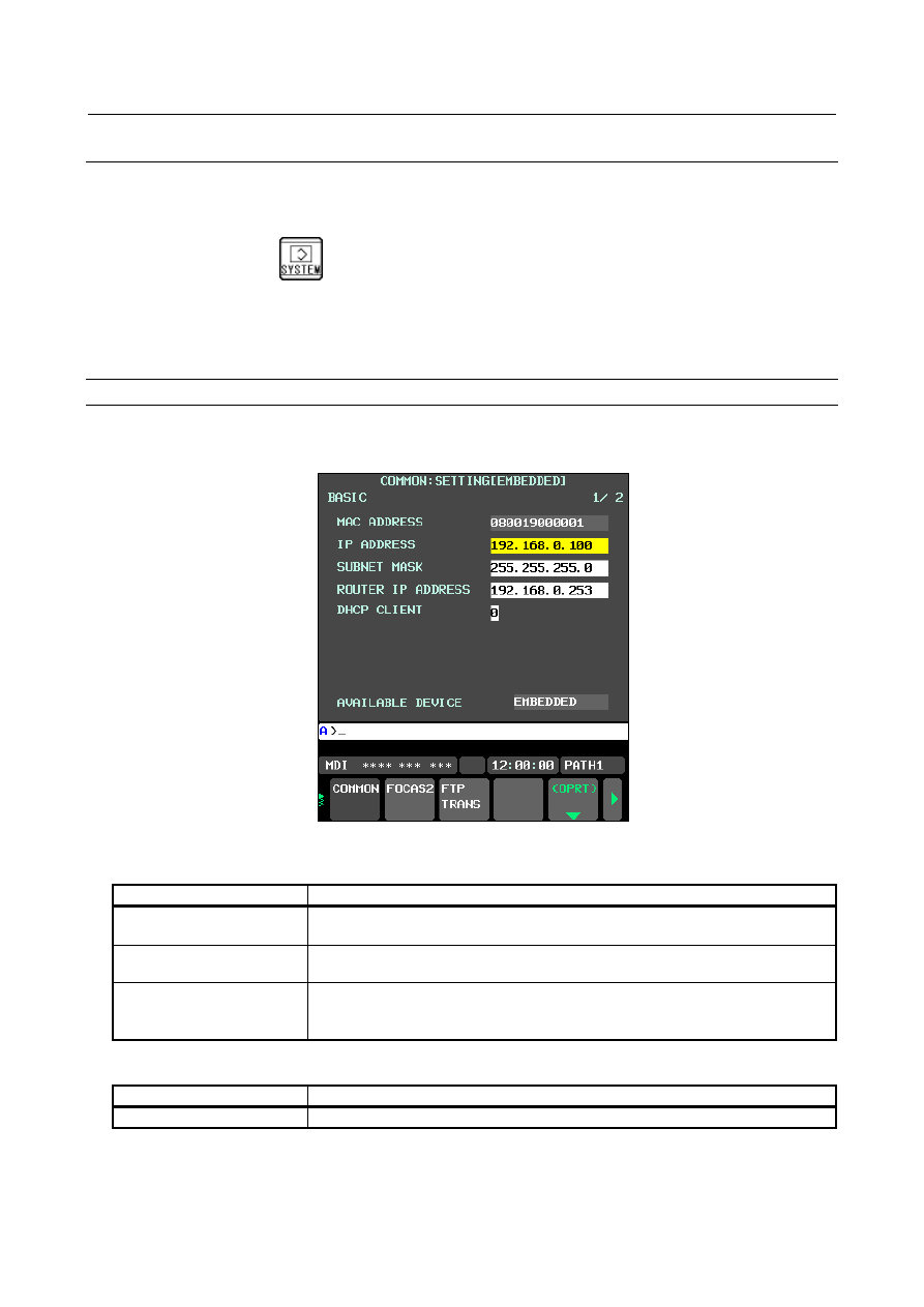
In the above-mentioned procedure, press soft key [COMMON] to display the COMMON screen 
(BASIC). 


Fig.17.2.9.2 (a) COMMON screen (BASIC) 


Setting items 

Item 

Description 

IP ADDRESS 

Specify the IP address of the embedded Ethernet. 
(Example of specification format: "192.168.0.100") 

SUBNET MASK 

Specify the mask address for the IP addresses of the network. 
(Example of specification format: "255.255.255.0") 

ROUTER IP ADDRESS 

Specify the IP address of the router. 
Specify this item if the network contains a router. 
(Example of specification format: "192.168.0.253") 


Display item 

Item 

Description 

MAC ADDRESS 

MAC address of the embedded Ethernet. 


B-64693EN-1/01


17. EMBEDDED ETHERNET FUNCTION


- 2739 - 

Setting Screen of the Modbus/TCP Server Function 

In the above-mentioned procedure, press soft key [Modbus SET] to display the setting screen of the 
Modbus/TCP Server function. 


Fig.17.2.9.2 (b) Setting screen 1 (BASIC) 

Fig.17.2.9.2 (c) Setting screen 2 (areas 1 to 3)   


Setting items 

Item 

Description 

PORT NUMBER (TCP) 

Specify the port number for using the Modbus/TCP Server function. 
The setting range is from 0 to 65535. Usually, set 502. When 0 is set, the 
Modbus/TCP Server function is not operated. 

OPTION1 

Bit 0: BCE 

The byte arrangement in the Modbus area is assumed to be 
0: little endian 
1: big endian 

Bits 1 to 7: RSV 

Be sure to set 0. 

STATUS PMC ADDRESS 

Specify the top address in the E/R area of the PMC in which to store the status. 
The setting range depends on the effective PMC area. A 1-byte area is used. 

DATA Modbus ADDRESS 

Specify the top address in the Modbus area (Holding registers) used to exchange 
I/O with the Modbus/TCP client. The setting range is 1 to 65536. 
For details of the endian of the data in the Modbus area (Holding Registers), see 
Subsection 18.2.6.1, "Conversion of Endian". 

DATA PMC ADDRESS 

Specify the top address in E/R/D area of the PMC used to exchange I/O with the 
Modbus/TCP client. 
The setting range depends on the effective PMC area. Only the even-numbered 
address can be set. 

DATA SIZE 

Specify the data size (unit: word size) used to exchange I/O with the Modbus/TCP 
client. The setting range depends on the effective PMC area. If not exchange I/O 
with the area, specify 0 for this parameter. 


17. EMBEDDED ETHERNET FUNCTION


B-64693EN-1/01


- 2740 - 

  WARNING 


When setting PMC address for Modbus/TCP server function, thoroughly confirm 
the content of “GENERAL WARNINGS FOR CNC APPLICATION 
DEVELOPMENT” in “SAFETY PRECAUTIONS” at the beginning of this manual. 


Be careful not to cause an overlap between the PMC area to allocate and a 
PMC area used for other purposes. 
If the machine is operated without confirmation of above explanation, the 
machine may behave unexpectedly, possibly damaging the tool, the machine 
itself, the workpiece, or causing injury to the user. 


NOTE 

1  For the changed parameters to take effect, turn the CNC power off and back on 

or restart embedded Ethernet at the COMMON screen. 

2  Communication parameters of the Modbus/TCP Server function that is operated 

on embedded Ethernet are included in the embedded Ethernet parameters. 

3  Set the Modbus areas for areas 1 to 3 so that they do not overlap. If any overlap, 

different actions are taken for READ and WRITE, as follows: 
For READ, area n where n is the largest is given priority, and data is read from 
that area. 
For WRITE, the same value is written to all the overlapping areas. 


Status 

The status (1 byte) is detected by the Modbus/TCP Server function. 


Status 


#7 

#6 

#5 

#4 

#3 

#2 

#1 

#0 

Status PMC address 

+0 

COM 

INT 

ERR 


Bit 

Name 

Description 

#0 

ERR 

Unrecoverable error 
0: The Modbus/TCP Server function is operating correctly. 
1: An unrecoverable error occurred in the Modbus/TCP Server function. 

#1-5 

-


Reserved 

#6 

INT


Initialization completion 
0: The initialization of the Modbus/TCP Server function is not completed. 
1: The initialization of the Modbus/TCP Server function is completed. 

#7 

COM 

Communicating 
0: Not communicating with a Modbus/TCP client. 
1: Communicating with one or more Modbus/TCP clients. 


B-64693EN-1/01


17. EMBEDDED ETHERNET FUNCTION


- 2741 - 

17.2.9.3 

MAINTENANCE 

This section describes the maintenance of the Modbus/TCP Server function. 
 

Maintenance Screen of the Modbus/TCP Server Function 

The connection status of the client connected to the Modbus/TCP Server can be checked on this screen. 
 

Procedure 

Press function key 

Soft key [EMBED PORT] appears. When the soft key does not appear, press the continue key. 

Press soft key [EMBED PORT], and then soft key [Modbus MAINTE] appears on the setting screen 
of the Ethernet function. 

Press soft key [Modbus MAINTE], and then  the maintenance screen (CLIENT LIST) of the 
Modbus/TCP Server function is displayed. 


Fig.17.2.9.3 (d) Maintenance screen (CLIENT LIST) of the Modbus/TCP Server function 


Display items 

Item 

Description 

CLIENT 

The IP addresses of the Modbus/TCP clients connected to this Modbus/TCP 
Server are displayed. (Example of display format: "192.168.0.200") 
They are displayed in the order in which the clients are connected. 

TIME 

The connecting times of the Modbus/TCP clients connected to this Modbus/TCP 
Server are displayed. The displayed times are updated automatically. 
The display format for a time of hour (hhh), minute (mm) and second (ss) is 
"hhh:mm:ss". The maximum value is "999:59:59", and if the maximum value is 
exceeded, the time will not be updated from "999:59:59". 


17. EMBEDDED ETHERNET FUNCTION


B-64693EN-1/01


- 2742 - 

17.2.9.4 

RELATED NC PARAMETER 


#7 

#6 

#5 

#4 

#3 

#2 

#1 

#0 

14882 


MOD 


[Input type]  Parameter input 


[Data type]  Bit


NOTE 


When this parameter is set, the power must be turned off before 
operation is continued. 


#1  MOD

  The Modbus/TCP Server function is used 

0: 

on a Fast Ethernet. 

1: 

on embedded Ethernet (embedded Ethernet port). 


17.3 

SWITCHING BETWEEN THE EMBEDDED ETHERNET 
DEVICES 

There are two types of embedded Ethernet devices: the embedded Ethernet port and PCMCIA Ethernet 
card. 
Screen operation is required to switch between these two types of devices. 
 

Procedure 

Press the function key 


Soft keys [EMBED] and [PCMCIA LAN] appear. 


(When there is no soft keys, press the continue key.) 

Press soft key [EMBED] or [PCMCIA LAN], press soft key [COMMON], and then press [(OPRT)] 
to display soft key [EMB/PCMCIA]. 

Pressing soft key [EMB/PCMCIA] switches between enabled devices. 


NOTE 

1  Information on a switched device is stored in nonvolatile memory.   
 

On the next power-on, the device last selected can be used as is. 

2  When using the unsolicited messaging function, note the following: 

-  Processing is forcibly started from the "Not Ready" state, regardless of the 

unsolicited message transfer state. 

-  When the parameter for control is set to use the response notification 

method, RES and RES_CODE (0x01) are posted to the ladder program. 

-  When the parameter for control is set to use the simplified method, REQ is 

cleared. 


B-64693EN-1/01


17. EMBEDDED ETHERNET FUNCTION


- 2743 - 

17.4 

RESTART OF THE EMBEDDED ETHERNET 

Communication using the embedded Ethernet can be restarted. 
 

Procedure 

Press the function key 


Soft keys [EMBED] and [PCMCIA] appear. 


(When there is no soft keys, press the continue key.) 

Press soft key [EMBED] or [PCMCIA LAN], press soft key [COMMON], and then press [(OPRT)] 
to display soft key [EMB/PCMCIA]. 

Pressing soft key [RSTART] resets embedded Ethernet communication and then restarts it. 


NOTE 

1  Pressing soft key [RSTART] forcibly interrupts communication even when it is in 

progress. 

2  This function makes a restart by software. An actual restart may be impossible 

under some conditions. 

3  When using the unsolicited messaging function, note the following: 

-  Processing is forcibly started from the "Not Ready" state, regardless of the 

unsolicited message transfer state. 

-  When the parameter for control is set to use the response notification 

method, RES and RES_CODE (0x01) are posted to the ladder program. 

-  When the parameter for control is set to use the simplified method, REQ is 

cleared. 


17.5 

MAINTENANCE SCREEN FOR EMBEDDED ETHERNET 
FUNCTION 

With the embedded Ethernet function, a dedicated maintenance screen is available. 
The maintenance screen enables operations to be checked when the embedded Ethernet function operates 
abnormally. 
 

Displaying and operating the PING screen 

Procedure 

Press the function key 


Soft keys [EMBED] and [PCMCIA LAN] appear. 


(When there is no soft keys, press the continue key.) 

By pressing the [EMBED] soft key, the Ethernet Setting screen for the embedded  Ethernet  is 
displayed. 


By pressing the [PCMCIA  LAN] soft key, the Ethernet Setting screen for the PCMCIA  Ethernet 
card can be set. 

Press soft key [PING] and then press [(OPRT)]. 

To send the PING command to connection destination 1 for FTP file transfer, press soft key [PING 
FTP1]. Similarly, to send the PING command to connection destination 2 or 3, press [PING FTP2] 
or [PING FTP3], respectively. 


17. EMBEDDED ETHERNET FUNCTION


B-64693EN-1/01


- 2744 - 


Fig. 17.5 (a) PING connection status screen 


To send the PING command to the desired destination, enter the address of the destination on the 

PING setting screen (Fig. 17.5(b)). (Page keys 


  are used for switching.) 


Fig. 17.5 (b) PING connection status screen 


After entering the address and the repeat count, press the soft key [PING]. The specified number of 
PING commands are sent to the specified destination.   

To cancel the PING command currently being sent, press soft key [PING CANCEL]. 


B-64693EN-1/01


17. EMBEDDED ETHERNET FUNCTION


- 2745 - 

Displaying Communication status screen 

Procedure 

Press the function key 


Soft keys [EMBED] and [PCMCIA LAN] appear.   


(When there is no soft keys, press the continue key.) 

By pressing the [EMBED] soft key, the Ethernet Setting screen for the embedded  Ethernet  is 
displayed. 


By pressing the [PCMCIA  LAN] soft key, the Ethernet Setting screen for the PCMCIA  Ethernet 
card can be set. 

To display the communication status (Fig. 17.5(c)) of the embedded Ethernet, press soft key [COM 
STATE]. 


Page keys 


  can be used to switch between the sending state and the receiving state. 


Fig. 17.5 (c) Communication status screen 


Display items 

Item 

Description 

BAUDRATE 

Displays the baud rate and transmission method.   
Transmission rate: 100Mbps or 10Mbps 
Transmission method: Full duplex or half duplex   
-------- : Not connected to HUB   

SEND PACKET 

Displays the number of transmitted packets. 

COLLISION 
CARRIER SENSE LOST 
DELAYOVER 
UNDERRUN 
SEND PARITY ERROR 

Displays the number of errors detected during transmission of packets.   

RECEIVE PACKET 

Displays the number of packets received.   

ALIGNMENT ERROR 
CRC ERROR 
OVERRUN ERROR 
FRAME LENGTH ERROR 
RECV PARITY ERROR 

Displays the number of errors detected during reception of packets.   

AVAILABLE DEVICE 

Currently available device of embedded Ethernet 

Displays either the embedded Ethernet port or the PCMCIA Ethernet card.   


Content      ..     346      347      348      349     ..