FANUC Series 0i-MODEL F Plus. CONNECTION MANUAL (FUNCTION) - page 307
 

  Index      Manuals     FANUC Series 0i-MODEL F Plus. CONNECTION MANUAL (FUNCTION) B-64693EN-1/01


Search            copyright infringement  


Content      ..     305      306      307      308     ..


FANUC Series 0i-MODEL F Plus. CONNECTION MANUAL (FUNCTION) - page 307


13. DISPLAY/SET/EDIT


B-64693EN-1/01


- 2410 - 

  - 

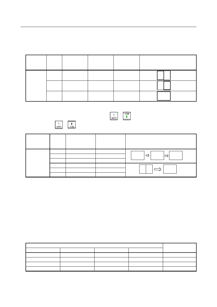
Switching by path select signal 

By setting bit 0 (PGR) of parameter No. 11304 to 1, the display group switching function based on the 
path select signals can be enabled. The simultaneous display group including a path selected with the path 
select signals is displayed. 
 

Number of 

CNC paths 

Path 

Display group 

number 

(Parameter 

No. 13131) 

Display order 

number 

(Parameter 

No. 13132) 

Path selected 

with the path 

select signals 

Screen display   

(The numbers in the illustration 

below represent path numbers.)   

(Box in heavy lines: Selected path) 

3 paths 

Path 1 


Path 2 


Path 3 


  - 

Switching by MDI key operation 

The display group can be sequentially switched by 


  (pressing PAGE DOWN while holding 

down SHIFT) or 


Number of 

CNC paths 

Path 

Display group 

number 

(Parameter No. 

13131) 

Display order 

number 

(Parameter No. 

13132) 

Screen display 

(The numbers in the illustration below 

represent path numbers.) 

(Example of SHIFT+PAGE DOWN) 

3 paths 

Path 1 


Path 2 

Path 3 

Path 1 


Path 2 

Path 3 


  - 

Path select signal 

The path select  signals are used to select  a path for which LCD/MDI operation  and  display  are to be 
performed. 
A path to be selected is determined using a combination of four signals. 
The following four signals (HEAD) are used: 


HEAD 

<G0063.0> 


HEAD2 

<G0062.7> 


HEAD3 

<G0408.1> 


HEAD4 

<G0408.2> 

 
The  table  below indicates the relationships between the combinations of the path select  signals and 
selected paths. 
 

Path select signal 

Selected path 

HEAD4 <G0408.2> 

HEAD3 <G0408.1> 

HEAD2 <G0062.7> 

HEAD <G0063.0> 

Path 1 

Path 2 

Path 3 

Path 4 


B-64693EN-1/01


13. DISPLAY/SET/EDIT


- 2411 - 

Parameter 

13131 


Group number for simultaneous display of multiple paths 


[Input type]  Parameter input 


[Data type]  Byte path 


[Valid data range]  0 to 4 

This  parameter  sets a group  for simultaneous display  on one screen  in a multi-path 
system.   
The paths set to belong to the same group are displayed on one screen. 
If the values for all paths are set to 0, the simultaneous multi-path display function is 
disabled. 
 

NOTE 


When specifying groups, specify group numbers not less than 1 
successively. 


On 8.4” and 10.4” display units, up to three paths can be specified 
for simultaneous display. 


On a 15” and 19” display units, up to four paths can be specified for 
simultaneous display. 


13132 


Simultaneous multi-path display order number 


[Input type]  Parameter input 


[Data type]  Byte path 

[Valid data range]  1 to number of paths included in a simultaneous multi-path display group 

This  parameter  sets the display  order of a path defined to belong to a simultaneous 
multi-path display group. 
Set the order, using numbers ranging from 1 to the number of paths included in the 
simultaneous multi-path display group. 


[Example]  Setting of simultaneous display group numbers and simultaneous display order numbers 

Number of 

paths of 

CNC


Path


Display 

group 

number


Intra-group 

display order 

number


Screen display 

(Numbers represent displayed path 

numbers.)


One path 

Path 1 


Three path 

Path 1 


Path 2 

Path 3 

Path 1 


Path 2 

Path 3 

Path 1 


Path 2 

Path 3 


NOTE 


Specify successive order numbers not less than 1 for the paths 
defined to belong to a group. 


1  2  3 


13. DISPLAY/SET/EDIT


B-64693EN-1/01


- 2412 - 


#7 

#6 

#5 

#4 

#3 

#2 

#1 

#0 

3208 


PSC 


[Input type]  Setting input 


[Data type]  Bit 


#5  PSC

  When the path is switched based on the path switch signal: 

0: 

The screen display is switched to the last selected screen of the path. 

1: 

The same screen as for the path before switching is displayed. 


#7 

#6 

#5 

#4 

#3 

#2 

#1 

#0 

11304 


PGR 


[Input type]  Parameter input 


[Data type]  Bit 


NOTE 


When this parameter is set, the power must be turned off before 
operation is continued. 


#0  PGR

  When the path select signal is changed, the screen of the multi path simultaneous display 

group: 
0: 

Is not switched. 

1: 

Is switched to the display group including the selected path. 


NOTE 


This parameter is initial setting parameter. For details, refer to the 
appendix "Automatic setting / Initial setting parameter" in this 
manual. 


Signal 

Path select signals   

HEAD<G063.0>, HEAD2<G0062.7>, HEAD3<G0408.1>, HEAD4<G0408.2> 

  [Classification]  Input signal 
 

[Function]  These signals select the target path for which MDI operation and display are to be 

performed. 
Operations with the MDI panel are performed for a path specified by the combination of 
HEAD, HEAD2, HEAD3, and HEAD4. 


Signal address 


#7 

#6 

#5 

#4 

#3 

#2 

#1 

#0 

G0062 


HEAD2 


G0063 


HEAD 


G0408 


HEAD4 

HEAD3 


B-64693EN-1/01


13. DISPLAY/SET/EDIT


- 2413 - 

13.3.2 

Simultaneous Multi Path Program Editing 

Overview 

Simultaneous multi path program editing allows the user to edit programs for more than one path on a 
single screen according to the settings of the simultaneous multi path display parameters (parameters 
Nos.13131 and 13132). 
This function is enabled by setting bit 0 (DHD) of parameter No. 3106. 
For details of parameter Nos. 13131 and 13132, see Subsection "Multi Path Display". 
 

Screen display 

Fig. 13.3.2 (a) to Fig. 13.3.2 (c) show sample screens on which simultaneous multi path program editing 
is being performed. 
The status line in the upper part of each program shows the name of the program, "FG-EDIT" indicating 
that foreground editing is in progress, and the path name. 
The status line of the currently edited program is highlighted. 


Fig. 13.3.2 (a) Simultaneous multi path program edit screen (10.4” display unit) 


Fig. 13.3.2 (b) Simultaneous multi path program edit screen (15” display unit) 

Program being 

edited 

13. DISPLAY/SET/EDIT


B-64693EN-1/01


- 2414 - 

Explanation 

  - 

Mode 

When the target paths for simultaneous display are in the EDIT mode or the MEM mode, the programs 
for these paths are displayed simultaneously on the program screen. When the EDIT mode is selected for 
a path, selecting that path allows program editing. 
Fig. 13.3.2 (c) shows an example in which the EDIT mode and MEM mode are set together. 
The first path is in the MEM mode (execution status screen), and the second path is in the EDIT mode 
(edit screen). 
Soft keys are displayed according to the mod of the path currently selected. 


Fig. 13.3.2 (c) Screen showing the MEM mode and EDIT mode 


  - 

Changing the path to be edited 

The path selected by the path selection signals is to be edited.


  - 

Maximum number of paths for which simultaneous editing is enabled 

The maximum number of paths for which simultaneous editing is enabled depends on the display unit as 
follows: 
 

Display unit size 

Maximum number of paths   

for simultaneous editing 

8.4 and 10.4” 

3 paths 

15 and 19” 

4 paths 


  - 

Conditions for disabling simultaneous editing 

Simultaneous multi path program editing is disabled in the following cases: 

The program screen is displayed with the entire screen size. 

The paths selected for simultaneous display include a path that is in a mode other than the EDIT and 
MEM modes. 

The virtual MDI key function is enabled. 

 
If background editing is started during simultaneous multi path program editing, background editing is 
performed with the entire screen size. Simultaneous multi path program editing and background editing 
cannot be performed at the same time. 
 

B-64693EN-1/01


13. DISPLAY/SET/EDIT


- 2415 - 

  - 

Simultaneous editing with a 8.4” display unit 

When simultaneous editing is performed with a 8.4” display unit, displayed characters become smaller. 
The number of characters displayed per path in the edit area is as follows: 

When simultaneous display is not performed, characters are displayed in 38 columns by 10 lines. 

For simultaneous display for one path, characters are displayed in 74 columns by 15 lines. 

For simultaneous display for two paths, characters are displayed in 35 columns by 14 lines. 

For simultaneous display for three paths, characters are displayed in 22 columns by 14 lines. 


Parameter 


#7 

#6 

#5 

#4 

#3 

#2 

#1 

#0 

3106 


DHD 


[Input type]  Setting input 


[Data type]  Bit 


#0  DHD

  On the program screen: 

0: 

Only a selected path can be edited and displayed. 

1: 

Multiple paths can be edited and displayed at the same time. 


13.4 

HIGH-SPEED PROGRAM MANAGEMENT 

Overview 

When many kinds of machining is arranged, this function can achieve the short processing time when 
many programs are registered collectively or all programs are deleted.  The program is not saved 
automatically to nonvolatile memory at registration, modification, or deletion of program. 
 

Explanation 

In  conventional  program management, the program is saved automatically to nonvolatile memory at 
registration, modification, or deletion of one program. Therefore, if many programs are registered at a 
time or all programs are deleted, all processing time becomes long, because automatic save is frequently 
done. 
 
In this function, if bit 7 (HPM) of parameter No.11354 is set to 1, the processing time of registering many 
programs or deleting all programs can be shorten because automatic save to nonvolatile memory is 
invalid. 
 
Perform saving operation by the all programs save request signal HPMRSV <G0514.4> or the application 
by FOCAS2/ C Language Library, if it is necessary that programs are saved to nonvolatile memory. 
 

Function 

Explanation 

cnc_saveprog_start 

Start saving program to nonvolatile memory. 

cnc_saveprog_end 

Check of end saving program to nonvolatile memory. 

 
The status that programs aren't saved to nonvolatile memory can be confirmed by the programs not saved 
status signal HPMNTS <F0547.5>.   
During the saving all programs to nonvolatile memory, the programs saving in progress signal HPMSVM 
<F0547.6> becomes "1". 
 

NOTE 

1  There are no changes about the display of programs and the editing operation 

method of programs. 

13. DISPLAY/SET/EDIT


B-64693EN-1/01


- 2416 - 

NOTE 

2  In cases that this function is enabled, if the power supply is turned off without 

saving, the changed programs data is not saved. 


The program selection by the following operation also is not saved. 
-  MDI operation 
-  External workpiece number search 
-  External program number search 


Please perform saving operation by the signal or the application by FOCAS2/ C 
Language Library, if it is necessary to preserve the changed programs data/ the 
program selection after the power supply is turned off. 

3  When the automatic operation signal is "1" in any path, the save operation is not 

executed. 

4  When the programs not saved status signal HPMNTS is "0", if the all programs 

save request to nonvolatile memory start, the save operation is not executed 
because of unnecessary. 

5  If the power supply is turned off during saving the programs programs (the 

programs saving in progress signal HPMSVM is "1"), all programs are deleted. In 
this case, an alarm PS0519 occurs when the power supply is turned on next. 

6  Do not save all programs to nonvolatile memory too frequently. 
7  In automatic data backup function, if this function is enabled, bit 2 (AAP) of 

parameter No.10340 should be set to 0. 

8  When the embedded macro program is registered, bit 7 (HPM) of parameter 

No.11354 should be set to 0. 

9  This function can be enabled only on CNC program storage memory 

(CNC_MEM device). 


B-64693EN-1/01


13. DISPLAY/SET/EDIT


- 2417 - 

The flow chart of all programs saving to nonvolatile memory by the signal 


The command of saving all programs to nonvolatile memory

(The all programs save request signal HPMRSV "0"->"1")

Is the programs not

saved signal HPMNTS "1"?

The saving operation end.

Is the automatic

operation signal OP "0"

in the all paths ?

The programs saving in progress

signal HPMSVM "0"->"1"

Is saving

operation success?

The programs saving in progress

signal HPMSVM "1"->"0"

The programs save error

signal HPMERR "0"->"1"

YES

YES

YES

NO

NO

NO

The the programs not saved signal

HPMNTS "1"->"0"


The time chart of all programs saving to nonvolatile memory by the signal 

The case of success 

Programs not saved

status signal

HPMNTS

All programs save

request signal

HPMRSV

Programs saving in

progress signal

HPMSVM

The programs are registered, edited, deleted, or changed of selection

Please confirm programs not saved status

signal,if the programs are saved.

After confirming the

complete of save


Content      ..     305      306      307      308     ..