FANUC Series 0i-MODEL F Plus. CONNECTION MANUAL (FUNCTION) - page 305
 

  Index      Manuals     FANUC Series 0i-MODEL F Plus. CONNECTION MANUAL (FUNCTION) B-64693EN-1/01


Search            copyright infringement  


Content      ..     303      304      305      306     ..


FANUC Series 0i-MODEL F Plus. CONNECTION MANUAL (FUNCTION) - page 305


13. DISPLAY/SET/EDIT


B-64693EN-1/01


- 2394 - 


Input the setting file of non-protected parameters 

Procedure 

1) 

Make sure the external I/O device is ready for input. 

2) 

Change to EDIT mode by operating the machine operator’s panel or enter emergency stop state. 

3) 

Enable operations on the setting screen for parameters.   

4) 

Press the return menu key. 

5) 

Press the soft key [NO-PRT PARAM]. NON-PROTECTED PARAMETER SETTING screen is 
displayed.   

6) 

Press the continuous menu key 

, and then press soft key [F INPUT]. 

7) 

Type the name of the file that you want to input.   

If the input file name is omitted, default input file name “MDPRMSET.TXT” is assumed. 

8) 

Press the soft key [EXEC].   

This starts input, and “INPUT” blinks in the lower right part of the screen. When the input operation 
ends, the “INPUT” indication disappears. 

9) 

After input has been finished, press the return menu key.   

10)  Press the soft key [PARAMETER]. The setting screen for parameters is displayed. 
11)  Press the soft key [REGISTER] to calculate the check code. 
12)  Press the soft key [LOCK] to disable operations. 


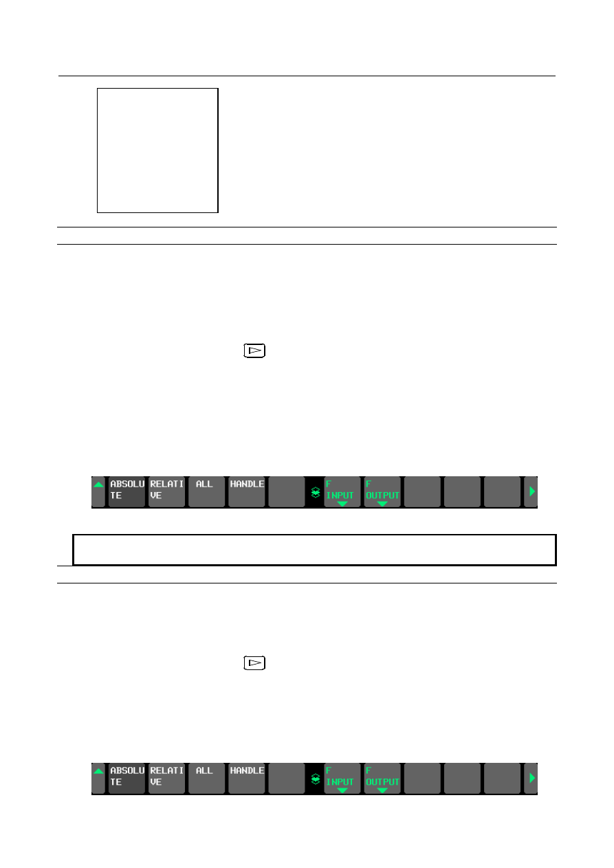
Fig 13.1.24.7 (d) Soft key of NON-PROTECTED PARAMETER SETTING screen (Page2) 


NOTE 


In the state of the "operation disabled", soft key [F input] is not displayed. 

Output the setting file of non-protected parameters 

Procedure 

1) 

Make sure the external I/O device is ready for output. 

2) 

Change to EDIT mode by operating the machine operator’s panel or enter emergency stop state. 

3) 

Press the soft key [NO-PRT PARAM]. NON-PROTECTED PARAMETER SETTING screen is 
displayed.   

4) 

Press the continuous menu key 

, and then press soft key [F OUTPUT]. 

5) 

Type the name of the file that you want to output.   

If the output file name is omitted, default output file name “MDPRMSET.TXT” is assumed. 

6) 

Press the soft key [EXEC].


This starts input, and “OUTPUT” blinks in the lower right part of the screen. When the input 
operation ends, the “OUTPUT” indication disappears. 

7) 

After output has been finished, press the return menu key. 


G10L99; 

N1S0E979; 

N2S983E1022; 

N3S1024E1239; 

N4S1241E1828; 

N5S1830E1837; 

N6S1843E99999; 

G11; 

B-64693EN-1/01


13. DISPLAY/SET/EDIT


- 2395 - 

Fig13.1.24.7 (e) Soft key of NON-PROTECTED PARAMETER SETTING screen (Page2) 


Parameters excluded from protected parameters 

Table 13.1.24.7 (a) Parameters excluded from protected parameters 

Parameter No. 

Description 

1244 

Coordinates of the floating reference position for each axis 

1301 

Stored stroke check 

1320 to 1321 

Coordinates at the boundary of stored stroke check 1 

1330 to 1348 

Chuck and tail stock barrier 

3233 

Program edit 

3281 

Displaying language 

3290 

Offset 

4803, 4840 to 4843 

Spindle position 

4911 to 4914 

Spindle speed fluctuation detection 

5130 

Cutting value (chamfering value) in thread cutting cycles G92 and G76 

5132 to 5133 

Depth of cut and escaping amount of multiple repetitive canned cycles G71 
and G72 

5134 

Clearance value of multiple repetitive canned cycle G71 and G72 

5135 

Escaping amount of X axis in multiple repetitive canned cycle G73 

5136 

Escaping amount of Z axis in multiple repetitive canned cycle G73 

5137 

Divide number of multiple repetitive canned cycle G73 

5139 

Return amount in multiple repetitive canned cycle G74 and G75 

5140 

Minimum depth of cut in multiple repetitive turning canned cycle G76 

5141 

Finishing allowance in multiple repetitive turning canned cycle G76 

5142 

Repetition count of final finishing in multiple repetitive turning canned cycle 
G76 

5143 

Tool nose angle in multiple repetitive turning canned cycle G76 

5402 

Manual handle interruption 

5660 to 5677 

Flexible synchronization control 

5680 to 5687, 5690 to 5693 

Flexible synchronization control 

6404 

Manual handle 

6510 

Specifying the graphic coordinate system 

6581 to 6595 

Color number of character 

6750 

Integrated value of power-on period 

7220 to 7283 

Name of general-purpose switch on software operator’s panel 

7310 

Program restart 

8210 

Slant angle 

8370 to 8374 

Oscillation 

8860 to 8861 

Trouble diagnosis function 

8900 

PWE 

8940 to 8949 

Initial screen title character code 

10000 to 10329 

Tool offsets 

10331 to 10332 

External workpiece zero point offsets 

10421 to 10435,   
10461 to 10475 

Screen display colors 

10601 to 10719 

Waveform diagnosis 

11221 

Tilted working plane indexing 

11309 

Menu number selected in pattern menu display 

11318 

Program list screen 

11329 to 11331, 11334 to 11337, 
11341 to 11349 

Dynamic graphic display function 

11355 to 11356 

Display 

11358 to 11359 

Parameter check sum 

11364 

Program edit 

11369 

Warning function against modification of setting 

13. DISPLAY/SET/EDIT


B-64693EN-1/01


- 2396 - 

Parameter No. 

Description 

11496 

Measurement result of thread groove 

11501 

Machine lock shift value check 

11505 

Code of Input/Output of data of USB memory 

12801 to 12820, 12841 to 12860 

Operation history signal selection 

13151 

Serial number for the files output to a memory card by external output 
command DPRNT/BPRNT 

13203 to 13204, 13206 

Tool management function 

13420, 13425 to 13440 

Flexible synchronization control 

14500 to 14637 

SERVO GUIDE Mate 

14717 

C axis’s number in simulation (for MGi) 


Table 13.1.24.7 (b) Parameters excluded from protected parameters   

(Machining condition selecting function is valid) 

Parameter No. 

Description 

1432 

Maximum cutting feedrate for all axes in the look-ahead acceleration / deceleration before 
interpolation 

1660 

Maximum allowable acceleration rate in look-ahead acceleration/deceleration before 
interpolation for each axis 

1735 

Maximum allowable acceleration rate for the deceleration function based on acceleration in 
circular interpolation for each axis (Only at the setting of No.13600#0=0) 

1737 

Maximum allowable acceleration rate for the deceleration function based on acceleration in 
AI contour control for each axis 

1769 

Time constant for acceleration/deceleration after cutting feed interpolation in the 
look-ahead acceleration/deceleration before interpolation mode 

1772 

Acceleration change time of look-ahead bell-shaped acceleration/deceleration before 
interpolation 

1783 

Maximum allowable feedrate difference for feedrate determination based on corner feedrate 
difference 

1788 

Maximum allowable acceleration change rate in feedrate determination based on 
acceleration change for each axis 

1789 

Maximum allowable acceleration change rate in feedrate determination based on 
acceleration change for each axis (linear interpolation) 

1790 

Ratio of change time of the rate of change of acceleration in look-ahead smooth bell-shaped 
acceleration/deceleration before interpolation 

13634 

Current precision level in AI contour control 


Table 13.1.24.7 (c) Parameters for setting the parameter numbers of parameters   

to be excluded from protected parameters (Machining condition selecting function is valid) 

Parameter explanation 

Parameter whose number is set in parameter No.13628 (Parameter number corresponding to arbitrary item 1 when 
AI contour control is used)


Parameter whose number is set in parameter No.13629 (Parameter number corresponding to arbitrary item 2 when 
AI contour control is used)


B-64693EN-1/01


13. DISPLAY/SET/EDIT


- 2397 - 

NOTE 

1  If machining condition selecting function is invalid, parameters in table 13.1.24.7 

(b) and table 13.1.24.7 (c) are contained in protected parameters   

2  If machining condition selecting function is invalid, parameters in table 13.1.24.7 

(d) are contained in protected parameters. 

3  The parameters of which numbers are set in parameter Nos. 13628 and 13629 

are excluded, but parameter Nos. 13628 and 13629 are not excluded. 

4  Setting parameters and locked parameters are contained in non-protected 

parameters. 

5  When the CNC software edition is changed, the alarm (DS5350) might be 

generated. In this case, register the parameter again.   


13.1.24.8 

Parameters 


#7 

#6 

#5 

#4 

#3 

#2 

#1 

#0 

11369 


MDP 

MDL 

MDC 


[Data type]  Bit 


#0  MDC

  MODIFICATION WARNING SETTING screen for C Language Executor is 

0: 

not displayed. 

1: 

displayed. 


#1  MDL

  MODIFICATION WARNING SETTING screen for PMC ladder is 

0: 

not displayed. 

1: 

displayed. 


#2  MDP

  MODIFICATION WARNING SETTING screen for parameters and non-protected 

parameters is 
0: 

not displayed. 

1: 

displayed. 


13.1.24.9 

Signals 

Notification signal for modification of C Language Executor program 

CDCEX <F0558.0> 

  [Classification]  Output signal 
 

[Function]  Notify the modification of C Language Executor program 

[Output condition] When this signal becomes 0, the program is not modified or not registered 
 

  When this signal becomes 1, the registered program is modified 


Notification signal for modification of 1st path PMC Ladder program 

CDLAD1 <F0558.1> 

  [Classification]  Output signal 
 

[Function]  Notify the modification of 1st path PMC Ladder program 

[Output condition] When this signal becomes 0, the program is not modified or not registered 
 

  When this signal becomes 1, the registered program is modified 


Notification signal for modification of 2nd path PMC Ladder program 

CDLAD2 <F0558.2> 

  [Classification]  Output signal 
 

[Function]  Notify the modification of 2nd path PMC Ladder program 

13. DISPLAY/SET/EDIT


B-64693EN-1/01


- 2398 - 

[Output condition] When this signal becomes 0, the program is not modified or not registered 
 

  When this signal becomes 1, the registered program is modified 


Notification signal for modification of 3rd path PMC Ladder program 

CDLAD3 <F0558.3> 

  [Classification]  Output signal 
 

[Function]  Notify the modification of 3rd path PMC Ladder program 

[Output condition] When this signal becomes 0, the program is not modified or not registered 
 

  When this signal becomes 1, the registered program is modified 


Notification signal for modification of Dual Check Safety PMC Ladder program 

CDDCL <F0558.4> 

  [Classification]  Output signal 
 

[Function]  Notify the modification of Dual Check Safety PMC Ladder program 

[Output condition] When this signal becomes 0, the program is not modified or not registered 

When this signal becomes 1, the registered program is modified 


Notification signal for modification of CNC parameter 

CDPRM <F0558.5> 

  [Classification]  Output signal 
 

[Function]  Notify the modification of selected CNC parameters 

[Output condition] When this signal becomes 0, any selected CNC parameters are not modified or 
 

  not registered 


  When this signal becomes 1, some selected CNC parameters are modified 


Notification signal for modification of 4th path PMC Ladder program 

CDLAD4 <F0558.6> 

  [Classification]  Output signal 
 

[Function]  Notify the modification of 4th path PMC Ladder program 

[Output condition] When this signal becomes 0, the program is not modified or not registered 
 

  When this signal becomes 1, the registered program is modified 


Notification signal for modification of 5th path PMC Ladder program 

CDLAD5 <F0558.7> 

  [Classification]  Output signal 
 

[Function]  Notify the modification of 5th path PMC Ladder program 

[Output condition] When this signal becomes 0, the program is not modified or not registered 
 

  When this signal becomes 1, the registered program is modified 


Signal address 


#7 

#6 

#5 

#4 

#3 

#2 

#1 

#0 

F0558 


CDLAD5 

CDLAD4 

CDPRM 

CDDCL 

CDLAD3 

CDLAD2 

CDLAD1 

CDCEX 


B-64693EN-1/01


13. DISPLAY/SET/EDIT


- 2399 - 

13.1.24.10 

Alarm and Message 

Number 

Message 

Contents 

DS5345 

C-EXECUTOR VERIFY ERROR 

C Language Executor program has been modified. 
Restore the registered program or register the 
modified program. 

DS5346 
DS5347 
DS5348 
DS5352 
DS5353 

LADDER PROGRAM VERIFY ERROR 

Ladder program has been modified. 
Restore the registered ladder program or register the 
modified ladder program. 

DS5349 

DCS LADDER PROGRAM VERIFY ERROR 

Ladder program of Dual Check Safety PMC has been 
modified. 
Restore the registered ladder program or register the 
modified ladder program. 

DS5350 

PARAMETER VERIFY ERROR 

CNC parameter has been modified. 
Restore the registered parameters or register the 
modified parameters. 


NOTE 


The following DS alarm numbers are corresponding to ladder program of 
multi-path PMC   
 

DS5346 = 1st path PMC ladder program 


DS5347 = 2nd path PMC ladder program 


DS5348 = 3rd path PMC ladder program 


DS5352 = 4th path PMC ladder program 


DS5353 = 5th path PMC ladder program 


13. DISPLAY/SET/EDIT


B-64693EN-1/01


- 2400 - 

13.1.25 

Title Display Function in Initial Screen 

Overview 

The character string (up to 10 characters) set by the parameter is displayed on the initial screen 
immediately after power-on.   
 

Details 

The character string set by parameter No.8940 to No.8949 can be displayed on the initial screen 
immediately after power-on as shown in the following figure 13.1.25 (a). ("ABCDE01234" is displayed 
in the example of figure) 


Fig.13.1.25 (a) Title display in initial screen

10.4” display unit


The character string is enclosed with the frame (* mark) and displayed. The color of the character is only 
white. It is possible to display up to ten characters, and the character that can be used is the following 
characters. 

0 to 9 
A to Z 
“-”

Negative sign


“.”

period


“  ”

space


B-64693EN-1/01


13. DISPLAY/SET/EDIT


- 2401 - 

The frame becomes small in proportion to the number of characters when character strings are less than 
10 characters. 
Character string, series name, and COPYRIGHT are displayed at the center for the 10.4” display unit. 
However, in 15” display unit, it is displayed as shown in the following figure 13.1.25 (b). 


Fig.13.1.25 (b) Title display in initial screen

15” display unit


When parameter No.8940-No.8949 is not set (When the parameter is all 0), the character string is not 
displayed. A conventional initial screen is displayed as shown in Figure 13.1.25 (c). 


Fig.13.1.25 (c) Initial screen

conventional display


NOTE 

1.  The character string is displayed also on the IPL screen. However, when the IPL 

menu screen ends, a conventional screen is displayed.   

2.  When the parameter is set by using "SRAM RESTORE" of the boot menu, the 

set character string is not displayed on an initial screen immediately after 
restore. It is necessary to restart CNC to display the character string. 


Content      ..     303      304      305      306     ..