FANUC Series 0i-MODEL F Plus. CONNECTION MANUAL (FUNCTION) - page 303
 

  Index      Manuals     FANUC Series 0i-MODEL F Plus. CONNECTION MANUAL (FUNCTION) B-64693EN-1/01


Search            copyright infringement  


Content      ..     301      302      303      304     ..


FANUC Series 0i-MODEL F Plus. CONNECTION MANUAL (FUNCTION) - page 303


13. DISPLAY/SET/EDIT


B-64693EN-1/01


- 2378 - 

(Example) 
 

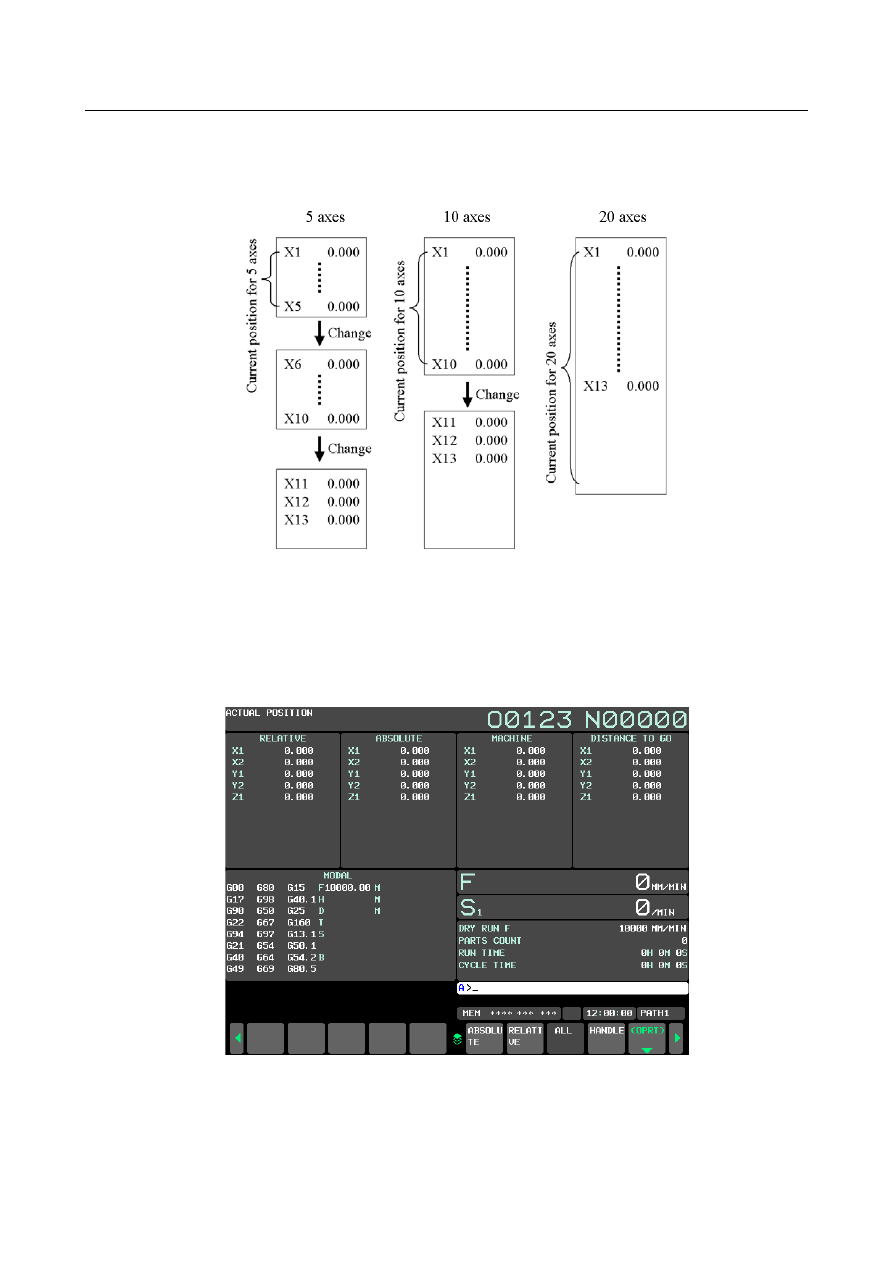
When 13 axes (X1 to X13) are displayed by each maximum number of simultaneous displaying axes, 

the display of coordinates is shown in following figures. 


Fig. 13.1.23 (a) Example when current position coordinates for 13 axes are displayed by number of maximum 

each axes. 


When the maximum number of simultaneous displaying axes is 5. 

The maximum number of simultaneous displaying axis becomes 5 by setting 0 to parameter No. 11305. 
When the number of axes exceeds 5, by pressing the chapter selection soft key, axes for the 6th axis and 
up are displayed. 


Fig. 13.1.23 (b) Current position display of 10.4 inch (overall) 


B-64693EN-1/01


13. DISPLAY/SET/EDIT


- 2379 - 


Fig. 13.1.23 (c) Current position display of 15 inch (overall) 


When the maximum number of simultaneous displaying axes is 10. 

The maximum number of simultaneous displaying axis becomes 10 by setting 1 to parameter No. 11305. 
When the number of axes exceeds 10, by pressing the chapter selection soft key, axes for the 11th axis 
and up are displayed. 


Fig. 13.1.23 (d) Current position display of 10.4 inch (overall) 


13. DISPLAY/SET/EDIT


B-64693EN-1/01


- 2380 - 


Fig. 13.1.23 (e) Current position display of 15 inch (overall) 


Addition of the chapter selection soft key in 15 inch 

The chapter selection soft key of "Absolute" and "Relative" is added setting 1 or 2 to parameter No. 
11305. 
When you press the chapter selection soft key of "Absolute", absolute coordinate is displayed with the 
character of 6 times size. 
When you press the chapter selection soft key of "Relative", relative coordinate is displayed with the 
character of 6 times size. 


Fig. 13.1.23 (i) Addition of the chapter selection soft key 


B-64693EN-1/01


13. DISPLAY/SET/EDIT


- 2381 - 


Fig. 13.1.23 (f) Current position display of 15 inch (relative) 


Change of display coordinates 

When the maximum number of simultaneous displaying axes is 20 (Parameter No.11305=2), Coordinates 
displayed in the position display of each screen at the same time are two pairs. The combination of two 
coordinates is decided by setting the order of displaying four coordinates systems displayed in overall 
position display screen (parameter No.11307). 
At power-on, the first combination of coordinate is displayed. You can change it   
 

the second one by pressing the chapter selection soft key  to selection after 


  key. When you do it 

again, the combination of coordinates is changed to the first one. 
(Example) 
 

The workpiece coordinate system setting screen of 10.4 inch. When parameter No.11307 is 4. The 
maximum number of simultaneous displaying axes is 20. 

13. DISPLAY/SET/EDIT


B-64693EN-1/01


- 2382 - 


Fig. 13.1.23 (g) Display change example in 10.4 inch. 


B-64693EN-1/01


13. DISPLAY/SET/EDIT


- 2383 - 

(Example) 
 

The workpiece coordinate system setting screen of 15 inch. When parameter No.11307  is 4. The 
maximum number of simultaneous displaying axes is 20. 


Fig. 13.1.23 (h) Display change example in 15 inch. 


13. DISPLAY/SET/EDIT


B-64693EN-1/01


- 2384 - 

About the function for which this function is effective 

This function is effective to positional coordinate screen concerning the following functions. 

Handle interruption 

Program restart 

Hypothetical axis 

Operating monitor display 

 
This function is ineffective to positional coordinate screen concerning the following functions 

3-dimensional manual feed 

Simultaneous display of multiple paths 


Parameter 

11305 


Maximum number of simultaneous displaying axes 


NOTE 


When at least one of these parameters is set, the power must be 
turned off before operation is continued. 


[Input type]  Parameter input 


[Data type]  Byte path 

[Valid data range]  0 to 2 

The maximum number of simultaneous displaying axes can be selected from 5, 10 and 20 
axes by setting this parameter. The table below indicates the correspondence between the 
max number of simultaneous displaying axes and the setting value. 
 

Maximum number of simultaneous displaying axes 

10 

20 

Setting 

When the value other than 1 and 2 is set, the specification of 0 is assumed. 
 

11307 


The order of displaying coordinates of current position display 


NOTE 


When at least one of these parameters is set, the power must be 
turned off before operation is continued. 


[Input type]  Parameter input 


[Data type]  Byte path 

[Valid data range]  0 to 5 

Set the order of coordinates displayed in the screen of the following size. 
10.4inch, 15inch 

-


Overall Position Display 

-


Overall Position Display of each screen 

 
When the maximum number of simultaneous displaying axes is 20 (Parameter 
No.11305=2), Coordinates displayed in the position display of each screen at the same 
time are two pairs. The combination of two coordinates is decided by setting the order of 
displaying four coordinates systems displayed in overall position display screen 
(parameter No.11307). 
At power-on, the first combination of coordinate is displayed. You can change it the 

second one by pressing selection chapter soft key to selection after 


  key. When you 

do it again, the combination of coordinates is changed to the first one. 
The correspondence of the order of the display and set value of coordinates is as follows. 

B-64693EN-1/01


13. DISPLAY/SET/EDIT


- 2385 - 

Order of displaying 

coordinates 

Setting Value 

Relative 

coordinates 

Absolute 

coordinates 

Machine 

coordinates 

Distance 

to go 

Relative 

coordinates 

Machine 

coordinates 

Absolute 

coordinates 

Distance 

to go 

Relative 

coordinates 

Distance 

to go 

Absolute 

coordinates 

Machine 

coordinates 

Absolute 

coordinates 

Machine 

coordinates 

Relative 

coordinates 

Distance 

to go 

Absolute 

coordinates 

Distance 

to go 

Relative 

coordinates 

Machine 

coordinates 

Machine 

coordinates 

Distance 

to go 

Relative 

coordinates 

Absolute 

coordinates 

 
When the value not within the valid data range is set, the specification of 0 is assumed. 
When simultaneous display of multiple path is effect (Parameter No.13131

0, parameter 

No.13132

1), this parameter is ineffective. 


13.1.24 

Warning


Function Against Modification of Setting 

13.1.24.1 

Overview 

This function is to protect important setting of parameters, C Language Executor programs, or ladder 
programs  on CNC and to detect unauthorized modifications on them. The following parameters and 
programs can be protected. 

CNC Parameters (which are selected to be protected) 

C Language Executor program 

Ladder program (each of multi-path PMC programs) 

Dual Check Safety PMC Ladder program 

After the registration of above parameters, C Language Executor programs, or ladder programs to this 
function, those are verified by CNC, when the power of CNC is turned on. If any modification is applied 
to registered parameters, C Language Executor programs, or ladder programs the signal that means some 
modification is applied is output. And in this case, it is also possible to generate the alarm. 
This is an optional function.   
 

Procedure for protecting parameters, C Language Executor programs, or ladder programs 

Procedure 

Preparation for registering protected parameters, C Language Executor programs, or ladder programs. 
1) 

Install C Language Executor programs or ladder programs to be protected into the flash ROM. 

2) 

Set the value of parameters to be protected. 

3) 

Edit the ladder program and Dual Check Safety ladder program, if necessary. 

 
Registration of protected parameters, C Language Executor programs, or ladder programs on setting   
screen. 
 
4) 

Enter password to enable operations on setting screen. (Refer to 13.1.24.3 and 13.1.24.4) 

By this operation, the following operations 5), 6), 7) are enabled. 

5) 

Change the setting of items, if necessary. (Refer to 13.1.24.2) 

6) 

Select the parameters to be protected. (Refer to 13.1.24.7) 

7) 

Register the parameters, C Language Executor programs, or ladder programs to be protected. (Refer 
to 13.1.24.3) 


After this operation, if any unauthorized modification to the selected parameters, C Language 
Executor programs, or ladder programs is detected, CNC outputs signal and alarm. 


Content      ..     301      302      303      304     ..