FANUC Series 0i-MODEL F Plus. CONNECTION MANUAL (FUNCTION) - page 308
 

  Index      Manuals     FANUC Series 0i-MODEL F Plus. CONNECTION MANUAL (FUNCTION) B-64693EN-1/01


Search            copyright infringement  


Content      ..     306      307      308      309     ..


FANUC Series 0i-MODEL F Plus. CONNECTION MANUAL (FUNCTION) - page 308


13. DISPLAY/SET/EDIT


B-64693EN-1/01


- 2418 - 

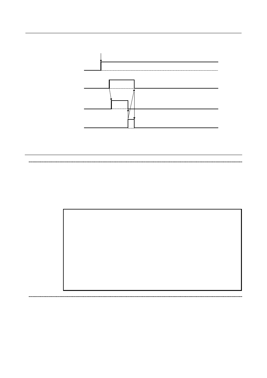
The case of error 

The programs are registered, edited, deleted, or changed of selection

Programs save error

signal

HPMERR

When the error occur,

HPMSVM becomes "0".

If HPMRSV is set to "0" from "1",

HPMERR becomes "0".

The not saved status remains because the error occurred.

Programs not saved

status signal

HPMNTS

All programs save

request signal

HPMRSV

Programs saving in

progress signal

HPMSVM


If the all programs save request signal HPMRSV is set to "1" from "0" in the automatic operation, the 
programs error signal becomes "1" at once.


Signal 

All programs save request signal HPMRSV <G0514.4> 

  [Classification]  Input signal 
 

[Function]  On high-speed program management, the save of all programs is requested by this signal.


[Operation]  When the programs not saved status signal HPMNTS is "1", if this signal is set to "1" 

from "0", the save of all programs to nonvolatile memory start. 
During program saving, the programs saving in progress signal HPMSVM is "1". 
This signal is effective when bit 7 (HPM) of parameter No.11354 is "1".


NOTE 

1  In the case of the following conditions, the save request does not 

start even if this signal is set to "1" from "0". 
-  When the automatic operation signal is "1" in any path. 
-  When the programs not saved status signal HPMNTS is "0". 
-  When the programs saving in progress signal HPMSVM is "1". 
-  When the automatic data backup executing signal ATBK is "1". 

2  If the power supply is turned off during saving the programs (the 

programs saving in progress signal HPMSVM is "1"), all programs 
are deleted. In this case, an alarm PS0519 occurs when the power 
supply is turned on next. Therefore, please preserve the backup of 
the programs in the external memory beforehand. 

3  Do not save all programs to nonvolatile memory too frequently. 


Programs not saved status signal HPMNTS <F0547.5> 

  [Classification]  Output signal 
 

[Function]  On high-speed program management, the signal indicates  the signal indicates the status 

that the programs are not saved.


[Operation]  When  the programs  are  registered, edited, deleted, or  changed  of selection, this signal 

becomes "1". 
If the programs are saved to nonvolatile memory by the all programs save request signal 
HPMRSV or the application by FOCAS2/ C Language Library, this signal becomes "0". 
This signal is effective when bit 7 (HPM) of parameter No.11354 is "1".


B-64693EN-1/01


13. DISPLAY/SET/EDIT


- 2419 - 

Programs saving in progress signal HPMSVM <F0547.6> 

  [Classification]  Output signal 
 

[Function]  On high-speed program management, the signal indicates the saving mode of the 

programs.


[Operation]  During saving the programs to nonvolatile memory by the all programs save request 

signal HPMRSV or the application by FOCAS2/ C Language Library, this signal become 
"1". When the saving operation ends, this signal becomes "0". 
This signal is effective when bit 7 (HPM) of parameter No.11354 is "1".


NOTE 

1  If the power supply is turned off when this signal is "1", all 

programs are deleted. In this case, an alarm PS0519 occurs when 
the power supply is turned on next. 

2  If the time of saving is extremely short, this signal might not 

become "1". 


Programs save error signal HPMERR <F0547.7> 

  [Classification]  Output signal 
 

[Function]  On high-speed program management, the signal indicates the occurrence of the programs 

saving error.


[Operation]  In the following condition when the programs saved by the all programs save request 

signal HPMRSV, this signal become "1" is requested, this signal becomes "1".   

When the automatic operation signal is "1" in either path. 

If the error is occurred, during saving to nonvolatile memory. 

If all programs save request signal HPMRSV is set to "0" from "1", this signal becomes 
"0". 
This signal is effective when bit 7 (HPM) of parameter No.11354 is "1".


Signal address 


#7 

#6 

#5 

#4 

#3 

#2 

#1 

#0 

G0514 


HPMRSV 


F0547 


HPMERR 

HPMSVM 

HPMNTS 


Parameter 


#7 

#6 

#5 

#4 

#3 

#2 

#1 

#0 

11354 


HPM 


[Input type]  Parameter input 


[Data type]  Bit 


NOTE 


When this parameter is set, the power must be turned off before 
operation is continued. 


#7  HPM

  High-speed program management is 

0: 

Disabled. 

1: 

Enabled. 


13. DISPLAY/SET/EDIT


B-64693EN-1/01


- 2420 - 

NOTE 

1  In cases that this function is enabled, if the power supply is turned off 

without saving, the changed programs data is not saved. 


The program selection by the following operation also is not saved. 
-  MDI operation 
-  External workpiece number search 
-  External program number search 


Please perform saving operation by the all programs save request 
signal HPMRSV or the application by FOCAS2/ C Language Library, 
if it is necessary to preserve the changed programs data/ the 
program selection after the power supply is turned off. 

2  When the automatic operation signal is "1" in any path, the save 

operation is not executed. 

3  Even if this parameter is changed from 1 to 0, automatic save of 

programs isn’t executed until the power supply will be turned on next. 

4  If the power supply is turned off during saving the programs (the 

programs saving in progress signal HPMSVM is "1"), all programs 
are deleted. In this case, an alarm PS0519 occurs when the power 
supply is turned on next. 

5  Do not save all programs to nonvolatile memory too frequently. 
6  In automatic data backup function, if this function is enabled, bit 2 

(AAP) of parameter No.10340 should be set to 0. 

7  When the embedded macro program is registered, bit 7 (HPM) of 

parameter No.11354 should be set to 0. 

8  This function can be enabled only on CNC program storage memory 

(CNC_MEM device). 


Alarm and message 

No. 

Message 

Description 

PS0519 

PROGRAM FILES ARE BROKEN AND 
CLEARED 

The program have been cleared, because the program 
were broken. The power supply might have been turned off 
while the program files is being saved to nonvolatile 
memory. 


B-64693EN-1/01


14. INPUT/OUTPUT OF DATA


- 2421 - 

14 

INPUT/OUTPUT OF DATA 

14.1 

RS-232C INTERFACE 

Overview 

The data shown below can be input/output through RS-232C interface. 
1. 

Program 

2. 

Offset data 

3. 

Parameter 

4. 

Pitch error compensation data 

5. 

Custom macro common variables. 

6. 

Workpiece coordinate system setting data 

7. 

Operation history data (output only) 

8. 

Tool management data 

 
The above data can be output to a memory card or USB memory via a memory card interface or USB 
memory interface.   
 
When a memory card is selected as the data input/output destination (parameter No. 20 = 4) at this time, if 
a file with the same file name already exists during writing of NC data such as programs or parameters, it 
is possible to select whether to overwrite the file or cancel the operation.   
To enable this function, set bit 1 (COW) of parameter No. 11308. 
 
When a USB memory is selected as the data input/output destination (parameter No. 20 = 17), a file with 
the same file name is already present during writing of NC data, the file is overwritten. 
 
The channel for data I/O is determined by setting parameter No. 0020. In this case, foreground or 
background data I/O is restricted to one channel. In addition, data I/O can be controlled separately by 
setting bit 0 (IO4) of parameter No. 0110. Concretely, a channel can be assigned to each of foreground 
input, foreground output, background input, and background output. 
 

Explanation 

The parameters described below must be set up to use an I/O unit interface (RS-232C  serial port) or 
memory card interface for inputting and outputting data (such as programs and parameters) between 
external input/output units and memory cards. 
The channel to which an I/O unit is connected needs be specified by setting I/O CHANNEL (parameter 
No. 0020). In addition, the specification number, baud rate, and number of stop bits of each I/O unit must 
be set in the parameter corresponding to each channel in advance. For setting of channel 1, two types of 
parameters for setting I/O units are provided. 
Channel setting can be made for each of foreground I/O and background I/O by setting bit 0 (IO4) of 
parameter No. 0110. At this time, channel setting is made with parameters Nos. 0020, 0021, 0022, and 
0023. 
The following shows correlation of interface parameters related to individual channels. 

14. INPUT/OUTPUT OF DATA


B-64693EN-1/01


- 2422 - 


Specify a channel for an data 
input/output device. 
I/O CHANNEL (0 to 17) 
   =0  :  Channel 1 
   =1  :  Channel 1 
   =2  :  Channel 2 


In addition, input/output of memory 
card interface is enabled. 

I/O CHANNEL = 0 

(Channel 1) 

0101 

0102 

0103 

Stop bit and other data 

Number specified for 
the input/output device 

Baud rate 

I/O CHANNEL = 2 

(Channel 2) 

0121 

0122 

0123 

Stop bit and other data 

Number specified for 
the input/output device 

Baud rate 

I/O CHANNEL = 1 

(Channel 1) 

0111 

0112 

0113 

Stop bit and other data 

Number specified for 
the input/output device 

Baud rate 

I/O CHANNEL 

or foreground input


0020 

Foreground output 

0021 

Background input 


0022 

Background output 


0023 

 
Channel settings are the same as 
with parameter No. 0020. 

When set by IO4 

I/O CHANNEL = 17 


Fig. 14.1 (a) Correlation of interface parameters related to individual channels 


Diagnosis 
 

  - 

Foreground 

030 


CHARACTER NUMBER DATA 

When the alarm SR0001, “TH ERROR”  occurred, the position in which it occurred is indicated by the 
number of characters counted from the beginning of the block. 
 

031 


TH DATA 

Readout code of the number of characters in which an alarm SR0001, “TH ERROR” occurred 
 

  - 

Background 

032 


CHARACTER NUMBER DATA 

When the alarm SR0001, “TH ERROR”  occurred, the position in which it occurred is indicated by the 
number of characters counted from the beginning of the block. 
 

033 


TH DATA 

Readout code of the number of characters in which an alarm SR0001, “TH ERROR” occurred 
 

B-64693EN-1/01


14. INPUT/OUTPUT OF DATA


- 2423 - 

Parameter 

0020 


I/O CHANNEL : Input/output device selection, or interface number for a foreground input device 


0021 


Foreground output device setting 


0022 


Background input device setting 


0023 


Background output device setting 


[Input type]  Setting input 


[Data type]  Byte 

[Valid data range]  0 to 17 

The  CNC  has the following  interfaces for transferring  data  to and from an external 
input/output device and the host computer: 

Input/output device interface (RS-232C serial ports 1 and 2) 

Memory card interface 

Data server interface 

Embedded Ethernet interface 

USB memory interface 

By setting bit 0 (IO4) of parameter No.  0110,  data  input/output  can be controlled 
separately. When IO4 is not set, data input/output is performed using the channel  set in 
parameter No.  0020. When IO4 is set, a channel  can be assigned to each of foreground 
input, foreground output, background input, and background output. 
In these parameters, specify the interface  connected  to each input/output  device  to and 
from which data is to be transferred. See the table below for these settings. 


Correspondence between settings and input/output devices 

Setting 

Description 

0,1 

RS-232C serial port 1 

RS-232C serial port 2 

Memory card interface 

Data server interface 

Embedded Ethernet interface 

17 

USB memory interface 


  - 

Parameters Common to all Channels 


#7 

#6 

#5 

#4 

#3 

#2 

#1 

#0 

0000 


ISO 

TVC 


[Input type]  Setting input 


[Data type]  Bit path 


#0  TVC

  TV check 

0: 

Not performed 

1: 

Performed 


#1  ISO

  Code used for data output 

0: 

EIA code 

1: 

ISO code 


14. INPUT/OUTPUT OF DATA


B-64693EN-1/01


- 2424 - 

NOTE 

1  The I/O setting of a memory card is made by bit 0 (ISO) of 

parameter No. 0139. 

2  The I/O setting of an USB memory is made by bit 0 (ISU) of 

parameter No. 11505. 

3  The I/O setting of a data server is made by bit 0 (ISO) of parameter 

No. 0908. 

4  When EIA code is used for data output (ISO = 0), set bit 3 (ASI) of 

parameter No.101 and 111 and 121 to 0. 


#7 

#6 

#5 

#4 

#3 

#2 

#1 

#0 

0010 


PEC 

PRM 

PZS 


[Input type]  Setting input 


[Data type]  Bit path 


#0  PZS

  When a part program is output, the O number is: 

0: 

Not zero-suppressed. 

1: 

Zero-suppressed. 


#1  PRM

  When parameters are output, the parameters whose values are 0 are: 

0: 

Output. 

1: 

Not output. 


#2  PEC

  When pitch error compensation data is output, the data whose value is 0 is: 

0: 

Output. 

1: 

Not output. 


#7 

#6 

#5 

#4 

#3 

#2 

#1 

#0 

0100 


ENS 

IOP 


NCR 

CRF 

CTV 


[Input type]  Setting input 


[Data type]  Bit 


#1  CTV

  Character counting for TV check in the comment section of a program. 

0: 

Performed 

1: 

Not performed 


#2  CRF

  Output of the end of block (EOB) in ISO code 

0: 

Depends on the setting of bit 3 (NCR) of parameter No. 0100. 

1: 

CR, LF are output. 


#3  NCR

  Output of the end of block (EOB) in ISO code 

0: 

LF, CR, CR are output. 

1: 

Only LF is output. 


#6  IOP

  Stopping a program output or input operation by a reset is: 

0: 

Enabled 

1: 

Disabled 


#7  ENS

  Action taken when a NULL code is found during read of EIA code 

0: 

An alarm is generated. 

1: 

The NULL code is ignored. 


B-64693EN-1/01


14. INPUT/OUTPUT OF DATA


- 2425 - 


#7 

#6 

#5 

#4 

#3 

#2 

#1 

#0 

0110 


IO4 


[Input type]  Parameter input 


[Data type]  Bit 


NOTE 


When this parameter is set, the power must be turned off before 
operation is continued. 


#0  IO4

  Separate control of I/O channel numbers is: 

0: 

Not performed. 

1: 

Performed. 

If the I/O channels are not separately controlled, set the input/output device in parameter 
No. 0020. 
If the I/O channels are separately controlled, set the input device and output device in the 
foreground and the input device and output device in the background in parameters Nos. 
0020 to 0023 respectively. 
Separate control of I/O channels makes it possible to perform background editing, 
program input/output, and the like during the DNC operation. 


#7 

#6 

#5 

#4 

#3 

#2 

#1 

#0 

0139 


ISO 


[Input type]  Setting input 


[Data type]  Bit 


#0  ISO

  When a memory card is selected as an I/O device, data input/output is performed using 

0: 

ASCII codes. 

1: 

ISO codes. 


  WARNING 

1  Unless data is input using ASCII codes, set this parameter to 1 to 

input or output data using ISO codes. 

2  Data input/output with ASCII codes is dangerous because parity 

information is not included and a data error during the data 
input/output is not detected. 

3  DNC operation from a memory card also must set the parameter to 

1, and execute DNC operation by ISO code. ASCII code is 
dangerous because parity information is not included and a data 
error during the data input is not detected. 


#7 

#6 

#5 

#4 

#3 

#2 

#1 

#0 

0908 


ISO 


[Input type]  Setting input 


[Data type]  Bit 


#0  ISO

  When a data server is selected as an I/O device, data input/output is performed using 

0: 

ASCII codes. 

1: 

ISO codes. 


Content      ..     306      307      308      309     ..