FANUC Series 0i-MODEL F Plus. CONNECTION MANUAL (FUNCTION) - page 299
 

  Index      Manuals     FANUC Series 0i-MODEL F Plus. CONNECTION MANUAL (FUNCTION) B-64693EN-1/01


Search            copyright infringement  


Content      ..     297      298      299      300     ..


FANUC Series 0i-MODEL F Plus. CONNECTION MANUAL (FUNCTION) - page 299


13. DISPLAY/SET/EDIT


B-64693EN-1/01


- 2346 - 

Explanation 

A name of up to eight characters can be assigned to 50 custom macro common variables #500 to #549 
using the following command. 
 

SETVN n[ VAR500,VAR501,VAR502,……] ; 

See Chapter II-16 in the OPERATOR’S MANUAL (B- 64694EN). 
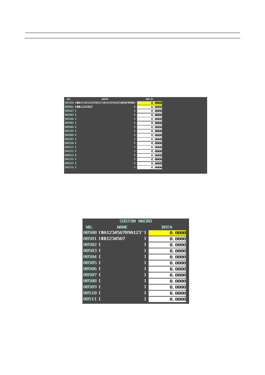
If this function is used, a custom macro common variable can have a variable name of up to 31 characters.   
Up to 31 characters can be displayed on the macro variable screen when:   


The full-screen display of the custom macro variable screen is performed on the 10.4-inch display.   


The custom macro variable screen is displayed on the 15-/19-inch display.   


Fig. 13.1.17 (a) 31-character display 

 
In the following cases, custom macro common variable names of up to 11 characters are displayed. If a 
macro variable name is longer than 11 characters, only the 11 characters are displayed and the rest is 
represented by "~". 


When the small-screen display of the custom macro variable screen is performed on the 10.4-inch 
display. 


Fig. 13.1.17 (b) 11-character display   


B-64693EN-1/01


13. DISPLAY/SET/EDIT


- 2347 - 

Display procedure 

1. 

Press the function key 


2. 

Press the continuous menu key 


  to display soft key [MACRO]. 

3. 

Press the soft key [MACRO].   


10.4-inch display unit 

The custom macro variable screen below is displayed.   
In small screen display, custom macro common variable names of up to 11 characters are displayed. 


Fig. 13.1.17 (c) 10.4-inch display (small screen display)   

 
Press soft key [MACRO] again to change the custom macro variable screen to full screen display. In full 
screen display, custom macro common variable names of up to 31 characters are displayed. 


Fig. 13.1.17 (d) 10.4-inch display (full screen display)   


13. DISPLAY/SET/EDIT


B-64693EN-1/01


- 2348 - 

NOTE 

1  Bit 4 (SCM) of parameter No. 11355 specifies whether small screen display or 

large screen display is selected in the initial state of the custom macro screen 
during power-on.   

2  If the pattern data input function is enabled and the comment of pattern data 

input is set to be displayed on the right side, variable names of up to 10 
characters are displayed in small screen display.   

3  If the macro compiler & executor function is enabled and custom macro common 

variables #500 to #549 and P-CODE macro common variables are set to be 
sharable, variable names of up to 31 or 11 characters are displayed on the 
execution macro variable screen, conversational macro variable screen, and 
auxiliary macro variable screen, as on the custom macro screen.   


15-inch display unit 

The custom macro variable screen below is displayed. Custom macro common variable names of up to 31 
characters are displayed. 


Fig. 13.1.17 (e) 15-inch display 


NOTE 


If the macro compiler & executor function is enabled and custom macro common 
variables #500 to #549 and P-CODE macro common variables are set to be 
sharable, variable names of up to 31 or 11 characters are displayed on the 
execution macro variable screen, conversational macro variable screen, and 
auxiliary macro variable screen, as on the custom macro screen.   


B-64693EN-1/01


13. DISPLAY/SET/EDIT


- 2349 - 

Parameter 


#7 

#6 

#5 

#4 

#3 

#2 

#1 

#0 

3207 


VRN 


[Input type]  Parameter input 


[Data type]  Bit 


#5  VRN

  On the custom macro variable screen, the variable names of common variables #500 to 

#549 are: 
0: 

Not displayed. 

1: 

Displayed. 


#7 

#6 

#5 

#4 

#3 

#2 

#1 

#0 

11355 


SCM 


[Input type]  Parameter input 


[Data type]  Bit 


#4  SCM

  In the initial state, the custom macro screen is: 

0: 

A small screen display. 

1: 

A full screen display. 


13.1.18 

Switching the Axis Name of an Axis Type Alarm 

Overview 

If an axis type alarm occurs, the type, number, and message of the alarm as well as the name of the axis 
on which the alarm occurred are displayed on the alarm screen. The axis name is usually the axis name set 
in parameter No. 1020, but bit 3 (DAA) of parameter No. 11368 can be set to switch the axis name to the 
one set in parameter No. 3132.   
 

Parameter 


#7 

#6 

#5 

#4 

#3 

#2 

#1 

#0 

11368 


DAA 


[Input type]  Parameter input 


[Data type]  Bit 


#3  DAA

  The axis name used with axis type alarms is one set using parameter No.: 

0: 

1020. 

1: 

3132. 


NOTE 

1  Even when this parameter is 1, an axis name set in parameter No. 

1020 is used if the value of parameter No. 3132 is 0. 

2  If an extended axis name is in use, only the first letter in it is 

replaced. 


Limitation 

Even when bit 3 (DAA) of parameter No. 11368 is 1, the axis name to be displayed on the operation 
history screen and the alarm history screen is the one set in parameter No. 1020. 
 

13. DISPLAY/SET/EDIT


B-64693EN-1/01


- 2350 - 

13.1.19 

Periodic Maintenance Screen 

Overview 

The periodic maintenance screen function provides guidelines as to when consumables such as the 
backup battery of the control unit and the backlight of the LCD unit are to be replaced and checked if the 
lifetimes of these items have been set in advance.


Signal 

Periodic maintenance lifetime warning signal LIFOVR<Fn093.0> 

  [Classification]  Output signal 
 

[Function]  Reports that a lifetime warning is issued on the periodic maintenance screen.


[Operation]  This signal is set to “1” when any of the items set on the periodic maintenance  screen 

enters the lifetime warning state.


Signal address 


#7 

#6 

#5 

#4 

#3 

#2 

#1 

#0 

Fn093 


LIFOVR 


Parameter 


#7 

#6 

#5 

#4 

#3 

#2 

#1 

#0 

8900 


PLC 


[Input type]  Setting input 


[Data type]  Bit path 


#3  PLC

   When the remaining time of an item falls to a value less than the percentage of the life 

specified in parameter No.8911, the life warning status is displayed at 
0: 

Timer area on CNC status display area. 

1: 

Alarm area on CNC status display area. 


#7 

#6 

#5 

#4 

#3 

#2 

#1 

#0 

8901 


MEN 


[Input type]  Setting input 


[Data type]  Bit path 


#7  MEN

  The periodic maintenance screen and the maintenance information screen are: 

0: 

Displayed. 

1: 

Not displayed. 


#7 

#6 

#5 

#4 

#3 

#2 

#1 

#0 

8903 


PDM 


[Input type]  Parameter input 


[Data type]  Bit path 


#0  PDM

  When  the remaining time of an item falls to a value less than the percentage of the life 

specified in parameter No.8911, the life warning status on CNC status display area is 


  0: 

Not displayed. 


  1: 

Displayed.


B-64693EN-1/01


13. DISPLAY/SET/EDIT


- 2351 - 


#7 

#6 

#5 

#4 

#3 

#2 

#1 

#0 

8906 


MPM 


[Input type]  Parameter input 


[Data type]  Bit 


NOTE 


When this parameter is set, the power must be turned off before 
operation is continued. 


#6  MPM

  On the periodic maintenance screen,   

0: 

the life time is counted in each path. 

1: 

the life time is not counted in each path. 


8911 


Percentage for life warning display on the periodic maintenance screen 


[Input type]  Parameter input 


[Data type]  Byte path 


[Unit of data]  % 

[Valid data range]  0 to 99 
 

  On the periodic maintenance screen, if the remaining time of an item falls to a value less 

than the percentage of the life specified in this parameter, the item name and remaining 
time is displayed in red as a warning. 


13.1.20 

Selection of display axis on the Current Position Screen 

Overview 

On the current position screen, it can be selected whether to display each axis position by setting the 
parameter or signal. 
Moreover, the order of displaying axis can be changed.


Explanation 

  - 

Selection of display axis 

If bit 0 (NDPx) of parameter No. 3115 is set to 1, the set axis is not displayed and the blank is displayed. 
 

  - 

Selection of display the absolute and relative coordinates and the 
distance-to-go 

If bit 1 (NDAx) of parameter No. 3115 is set to 1, the absolute and relative coordinates and the 
distance-to-go is not displayed. (The machine coordinates are displayed) 
 

  - 

Change the order of displaying axis 

If parameter No. 3130 is set, the order of displaying each axis can be changed. 
 

NOTE 

1  The order can be changed only in the current position screen, and it is 

impossible in other screens such as the work-offset screen and the parameter 
screen. 

2  If the parameters of all axes are set to 0, this function is invalid. 
3  The axis that 0 or value more than number of maximum axes in the path is set to 

the parameter is not displayed. 


13. DISPLAY/SET/EDIT


B-64693EN-1/01


- 2352 - 

  - 

Close up display 

If bit 0 (TAD) of parameter No. 13102 is set to 1, when the axis is not displayed by the bit 0 (NDPx) of 
parameter No. 3115, the axes are closed up and displayed. 
Moreover, when the order of displaying axes are changed by parameter No. 3130, the axis that 0 is set to 
the parameter is closed up and displayed. 
 

  - 

Selection of display axis by the signal 

If the axis non-displayed signal NPOS1 to NPOS8 <Gn198> is set to “1”, the set axis is not displayed and 
the blank is displayed. 
 

NOTE 


If bit 0 (TAD) of parameter No. 13102 is set to 1, when the axis non-displayed 
signal NPOS1 to NPOS8 <Gn198> is set to “1”, the axis is closed up. 


Parameter 


#7 

#6 

#5 

#4 

#3 

#2 

#1 

#0 

3115 


NDAx 

NDPx 


[Input type]  Parameter input 


[Data type]  Bit axis 


#0  NDPx

  The current position is: 

0: 

Displayed. 

1: 

Not displayed. 


NOTE 


When using the electronic gear box (EGB) function, set 1 for the 
EGB dummy axis to disable current position display. 


#1  NDAx

  The current position and the amount of the movement to be made in absolute and relative 

coordinates are: 
0: 

Displayed. 

1: 

Not displayed. (The machine coordinates are displayed.) 


3130 


Axis display order for current position display screens 


[Input type]  Parameter input 


[Data type]  Byte axis 

[Valid data range]  0 to 32 

Set the order in which axes are displayed on current position display screens. 


#7 

#6 

#5 

#4 

#3 

#2 

#1 

#0 

13102 


TAD 


[Input type]  Parameter input 


[Data type]  Bit path 


NOTE 


When at least one of these parameters is set, the power must be 
turned off before operation is continued. 


#0  TAD

  When the axis is not displayed by the bit 0 (NDPx) of parameter or parameter No.3130,   

0: 

The set axis is displayed as blanks. 

1: 

The axis is closed up and displayed. 


B-64693EN-1/01


13. DISPLAY/SET/EDIT


- 2353 - 

Signal 

Axis non-displayed signals NPOS1 to NPOS8<Gn198> 

  [Classification]  Input signal 
 

[Function]  The display axis on the current position screen is selected. 


[Operation]  When these signals are set to “0”, the set axes are displayed. 


  When these signals are set to “1”, the set axes are not displayed.


Signal address 


#7 

#6 

#5 

#4 

#3 

#2 

#1 

#0 

Gn198 


NPOS8 

NPOS7 

NPOS6 

NPOS5 

NPOS4 

NPOS3 

NPOS2 

NPOS1 


13.1.21 

Power Consumption Monitor 

Function Overview 

The electric power consumption and integral power consumption of servo motor and spindle motor can be 
read through the interface of PMC window, FOCAS2 interface or etc.    Custom application can observe 
consumed power and regenerative power of servo and spindle axes. Then you can use them to appeal 
your machine with the energy saving ability. Moreover, these values can be confirmed on the CNC 
screen. 
Because the power consumption data is in the diagnosis data, it is possible to read it from user's 
application in the following way. For the details, please refer to each manual. 
 

PMC 
WINDR function code 33 

Reading diagnosis data (Low-speed) 

For details of the WINDR instruction, please refer to PMC programming manual (B-64513EN). 


FOCAS2 function 
cnc_diagnoss   


Read diagnosis data 

cnc_diagnosr   


Read diagnosis data(area specified) 

For details of the function specification, please refer to a data window library specifications 

bundled to FOCAS1/2 Library disk (A02B-0207-K737). 


C language executor 
cnc_diagnoss   


Read diagnostics data 

For details of the function specification, please refer to C Language Executor programming 

manual (B-63943EN-3). 


Content      ..     297      298      299      300     ..