FANUC Series 0i-MODEL F Plus. CONNECTION MANUAL (FUNCTION) - page 300
 

  Index      Manuals     FANUC Series 0i-MODEL F Plus. CONNECTION MANUAL (FUNCTION) B-64693EN-1/01


Search            copyright infringement  


Content      ..     298      299      300      301     ..


FANUC Series 0i-MODEL F Plus. CONNECTION MANUAL (FUNCTION) - page 300


13. DISPLAY/SET/EDIT


B-64693EN-1/01


- 2354 - 

Displaying power consumption   

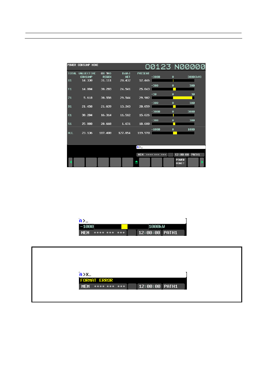
Power consumption monitoring screen   

The electric power data of servo axis and spindle axis consumption and regeneration can be displayed. 


Fig.13.1.21 (a) Power consumption monitoring screen for 10.4” display unit   

 
Refer to Operator’s Manual (Common to Lathe System/Machining Center System) (B-64694EN) for 
detailed operations on Power consumption monitoring screen. 
 

Bar-graph display of whole power consumption 

The bar-graph where the entire power consumption can be confirmed is displayed in the warning message 
area. Power consumption can be confirmed on every screen. 


Fig.13.1.21 (b) Bar-graph of entire power consumption 


NOTE 

1  The bar-graph display can be concealed by the setting of parameter APM 

(No.11368#6)=1. 

2  When the warning message is displayed, the bar-graph is not displayed. 


3  The bar-graph displayed in the warning display area is only the entire power 

consumption. 


B-64693EN-1/01


13. DISPLAY/SET/EDIT


- 2355 - 

Diagnosis data 

Present power consumption of all axes 

4900 


Present power consumption of all axes 


[Data type]  2-Word 


[Unit of data]  W 

[Valid data range]  -99999999 to 99999999 
 

Present power consumption of each servo axis 

4901 


Present power consumption of each servo axis 


[Data type]  2-Word axis 


[Unit of data]  W 

[Valid data range]  -99999999 to 99999999 


NOTE 


This value becomes negative during regeneration of power that is 
generated by deceleration of an axis   


Present power consumption of each spindle axis 

4901 


Present power consumption of each spindle axis 


[Data type]  2-Word spindle 


[Unit of data]  W 

[Valid data range]  -99999999 to 99999999 


NOTE 


This value becomes negative during regeneration of power that is 
generated by deceleration of an axis 


Integral power consumption of all axes 

4910 


Integral net power consumption of all axes 


4911 


Integral power consumption of all axes 


4912 


Integral power regeneration of all axes 


[Data type]  2-Word 


[Unit of data]  0.001kWh 

[Valid data range]  -99999999 to 99999999 


13. DISPLAY/SET/EDIT


B-64693EN-1/01


- 2356 - 

NOTE 

-  These values are integrated from 0.000kWh every turning on CNC.   
-  No.4911 and No.4912 are counted as “consumption” when the 

summational power of all axes is positive value and counted as 
“regeneration” when the summational power of all axes is negative 
value. This shows the result of including countervailing among all 
axes in case that some axes consume power but other axes 
regenerate power. Therefore these diagnosis data mean the net 
consumption and net regeneration power exchanging between the 
power supply and commercial power source. 
Example) 
 

Assume that the case of power 


in a spindle axis: consumption 100kWh, regeneration 25kWh 


in a servo axis: consumption 20kWh, regeneration 1kWh 


The result of simple summation becomes consumption 120kWh 
and regeneration 26kWh. 


In this situation, assume that 1kWh power consumption in the 
spindle axis and 1kWh power regeneration in the servo axis 
occurs simultaneously. The each 1kWh is countervailed. As a 
result, integral power consumption becomes 119kWh and the 
integral power regeneration becomes 25kWh and the integral net 
power consumption becomes 94kWh. 


Integral power consumption of each servo axis 

4920 


Integral net power consumption of each servo axis 


4921 


Integral power consumption of each servo axis 


4922 


Integral power regeneration of each servo axis 


[Data type]  2-Word axis 


[Unit of data]  0.001kWh 

[Valid data range]  -99999999 to 99999999 


NOTE 


These values are integrated from 0.000kWh every turning on CNC.   


Integral power consumption of each spindle axis 

4930 


integral net power consumption of each spindle axis 


4931 


integral power consumption of each spindle axis 


4932 


integral power regeneration of each spindle axis 


[Data type]  2-Word spindle 


[Unit of data]  0.001kWh 

[Valid data range]  -99999999 to 99999999 


NOTE 


These values are integrated from 0.000kWh every turning on CNC.   


B-64693EN-1/01


13. DISPLAY/SET/EDIT


- 2357 - 

Parameter 


#7 

#6 

#5 

#4 

#3 

#2 

#1 

#0 

2281 


RDPRR 

RDPMU2 

RDPMU1 


[Input type]  Parameter input 


[Data type]  Bit axis 


#0 RDPMU1


#1 RDPMU2

  Internal unit setting of power consumption monitor 


  Please set these bits according to the maximum motor output. 


Table 13.1.21 (a) Internal unit setting (Servo) 

Maximum output of motor 

RDPMU2 

RDPMU1 

 300kW or more 

  30kW to 300kW 

  3kW to  30kW 

3kW or less 


Table 13.1.21 (b) Setting for each servo motor 


Servo Motor 


  RDPMU2 

RDPMU1 

α

i

S500/3000HV 

    *2


α

i

S1000/2000HV  


*2


α

i

S1000/3000HV 

  *2


α

i

S2000/2000HV 


*1,2


α

i

S3000/2000HV

  *1,2


α

i

F40/3000 

α

i

F40/3000FAN 

α

i

S12/6000 

α

i

S12/6000HV 

α

i

S22/4000 

α

i

S22/4000HV 

α

i

S22/6000 

α

i

S22/6000HV 

α

i

S30/4000 

α

i

S30/4000HV 

α

i

S40/4000 

α

i

S40/4000HV 

α

i

S50/2000 

α

i

S50/2000HV 

α

i

S50/3000FAN 

α

i

S50/3000HVFAN 

α

i

S60/2000 

α

i

S60/2000HV 

α

i

S60/3000FAN 

α

i

S60/3000HVFAN 

α

i

S100/2500 

α

i

S100/2500FAN 

α

i

S100/2500HV 

α

i

S100/2500HVFAN 

α

i

S200/2500 

α

i

S200/2500FAN 

α

i

S200/2500HV 

α

i

S200/2500HVFAN 

α

i

S300/2000      

*2


α

i

S300/2000HV   

*2


α

i

S300/3000HV 

α

i

S500/2000      

*2


α

i

S500/2000HV   

*2


α

i

F2/5000 

α

i

F4/4000 

α

i

F4/4000HV 

α

i

F8/3000 

α

i

F8/3000HV 

α

i

F12/3000 

α

i

F12/3000HV 

α

i

F22/3000 

α

i

F22/3000HV 

α

i

F30/3000 

α

i

S2/5000 

α

i

S2/5000HV 

α

i

S2/6000 

α

i

S2/6000HV 

α

i

S4/5000 

α

i

S4/5000HV 

α

i

S4/6000 

α

i

S4/6000HV 

α

i

S8/6000 

α

i

S8/6000HV 

α

i

S8/4000 

α

i

S8/4000HV 

α

i

S12/4000 

α

i

S12/4000HV 

β

i

S1/6000 

β

i

S4/4000 

β

i

S4/4000HV 

β

i

Sc4/4000 

β

i

S8/3000 

β

i

S8/3000HV 

β

i

Sc8/3000 

β

i

S12/2000 

β

i

S12/3000 

β

i

S12/3000HV 

β

i

Sc12/3000 

β

i

S22/2000 

β

i

S22/2000HV 

β

i

S22/3000 

β

i

S22/3000HV 

β

i

S30/2000 

β

i

S30/2000HV 

β

i

S40/2000 

β

i

S40/2000HV


α

i

F1/5000 

β

i

S0.2/5000


β

i

S0.3/5000 

β

i

S0.4/5000 

β

i

S0.5/6000 

β

i

S2/4000 

β

i

S2/4000HV 

β

i

Sc2/4000


13. DISPLAY/SET/EDIT


B-64693EN-1/01


- 2358 - 

Synchronous built-in servo motor

 *3


  RDPMU2 

RDPMU1 


D

i

S1500/250(400V) 

D

i

S2000/150(400V) 

D

i

S5000/50(400V)


D

i

S15/1000(400V) 

D

i

S60/400(400V) 

D

i

S70/300(400V) 

D

i

S85/1000(200V) 

D

i

S110/1000(200V) 

D

i

S150/300(200V) 

D

i

S150/300(400V) 

D

i

S200/300(200V) 

D

i

S200/300(400V) 

D

i

S250/250(200V) 

D

i

S250/250(400V) 

D

i

S260/300(400V) 

D

i

S260/1000(200V) 

D

i

S370/300(200V) 

D

i

S370/300(400V) 

D

i

S400/250(200V) 

D

i

S400/250(400V) 

D

i

S500/250(200V) 

D

i

S500/250(400V) 

D

i

S800/250(200V) 

D

i

S800/250(400V) 

D

i

S1000/200(200V) 

D

i

S1000/200(400V) 

D

i

S1200/250(200V) 

D

i

S1200/250(400V) 

D

i

S1500/100(200V) 

D

i

S1500/100(400V) 

D

i

S1500/250(200V) 

D

i

S2000/100(200V)


D

i

S2000/100(400V) 

D

i

S2000/150(200V) 

D

i

S15/1000(200V) 

D

i

S22/600(200V) 

D

i

S22/600(400V) 

D

i

S22/1500(200V) 

D

i

S60/400(200V) 

D

i

S70/300(200V) 

D

i

S85/400(200V) 

D

i

S85/400(400V) 

D

i

S110/400(200V) 

D

i

S110/400(400V) 

D

i

S260/300(200V)


Linear motor   

*4


  RDPMU2 

RDPMU1 


L

i

S17000C3/2(400V) 


L

i

S1500B1/4(200V) 

L

i

S3000B2/2(200V) 

L

i

S3000B2/2(400V) 

L

i

S3000B2/4(200V) 

L

i

S4500B2/2(200V) 

L

i

S4500B2/2(400V) 

L

i

S4500B2/2HV 

L

i

S6000B2/2(200V) 

L

i

S6000B2/2(400V) 

L

i

S6000B2/2HV 

L

i

S6000B2/4(200V) 


L

i

S7500B2/2(200V) 

L

i

S7500B2/2(400V) 

L

i

S7500B2/2HV 

L

i

S9000B2/2(200V) 

L

i

S9000B2/2(400V) 

L

i

S9000B2/4(200V) 

L

i

S3300C1/2(200V) 

L

i

S3300C1/2(400V) 

L

i

S9000C2/2(200V) 

L

i

S9000C2/2(400V) 

L

i

S9000C2/2HV 

L

i

S11000C2/2(200V) 

L

i

S11000C2/2(400V) 

L

i

S11000C2/2HV 

L

i

S15000C2/2(200V) 

L

i

S15000C2/2(400V) 

L

i

S15000C2/3(200V) 

L

i

S15000C2/3HV 

L

i

S10000C3/2(200V) 

L

i

S10000C3/2(400V) 

L

i

S10000C3/2HV 

L

i

S17000C3/2(200V) 

L

i

S17000C3/2HV


L

i

S300A1/4(200V) 

L

i

S600A1/4(200V) 

L

i

S900A1/4(200V)


*1)  Power Consumption Monitor is not available to the axis using 

α

i

S3000/2000HV or 

α

i

S2000/2000HV with torque control. 

*2)  In the case of “plural winding motor”, which is a motor driven by 2 or 4 amplifiers, 

please set the following parameters for main axis only. (Please set to 0 for sub axis) 

*3)  In the case of synchronous built-in servo motors, please set No.2300#2=1. If you use 

a non-binary type encoder, please set No.2010#2=1 at the same time. 

*4)  In the case of linear motors, please set No.2010#2=1.   
*5)  Regarding the other motors, please set it according to the maximum motor output 

described in each motor manual. 


NOTE 


If these bits are wrong, the electric power consumption data is not 
calculated correctly.   


#2  RDPRR

  Regeneration method of servo amplifier is 

0: 

regeneration to power source   

1: 

register regeneration 


B-64693EN-1/01


13. DISPLAY/SET/EDIT


- 2359 - 

NOTE 


In case of using the amplifier with register regeneration, regeneration 
power is not returned to power source. Therefore, instantaneous 
power consumption should become greater than 0. 


2468 


RDPMR Motor winding resistance 


[Input type]  Parameter input 


[Data type]  Word axis 


[Unit of data]  2

-12

Ω


Please set the value of “Armature resistance (1 phase)” in the specifications of the motor. 
Example) Case of 

α

i

 S8/4000 


Set value=0.31/2

12 

=1270 where armature resistance=0.31

Ω


NOTE 

1  Be sure to set this parameter. Power consumption calculation works 

when this parameter is set to more than 1.   

2  Power consumption calculation works on main axis only in case of 

the motor with plural winding. Set this parameter for a main axis 
only. Set 0 for sub axis. 


2469 


RDPMA Lose coefficient A of a servo amplifier 


[Input type]  Parameter input 


[Data type]  Word axis 

Please set the value of loss coefficient A in Table Table 13.1.21 (c) . 
Example) Case of 

α

i

 SV80-B, Set value=832 


Case of 

α

i

 SV80/80-B, Set value (L axis) = 672, Set value (M axis) = 672 


13. DISPLAY/SET/EDIT


B-64693EN-1/01


- 2360 - 

NOTE 

1  Set this value only to main axis in case of a plural winding motor. 

Set 0 to the sub axis.   

2  When you use Serial feedback dummy function with servo 

amplifier, add RDPMA value of dummy axis to No.2469 of other 
non-dummy axis. 


2490 


RDPMB Lose coefficient B of a servo amplifier 


[Input type]  Parameter input 


[Data type]  Word axis 

Please set the value of loss coefficient B in Table Table 13.1.21 (c) .   
Example) Case of 

α

i

 SV80-B, 

α

i

 SV80/80-B HRV2, Set value=262 


Case of 

α

i

 SV80-B, 

α

i

 SV80/80-B HRV3, Set value=352 


NOTE 

1  Setting value depends on HRV. 
2  Set this value only to main axis in case of a plural winding motor. 

Set 0 to the sub axis. 


Table 13.1.21 (c) Loss coefficient A, B setting value of servo amplifier 

In case of multi-axis amplifier, please set the value corresponding to each axis. If there 
are two columns, the upper column corresponds to L axis and the lower correspond to M 
axis. If there are three columns, each corresponds to L, M and N axis from the upper. 

Name 

Spec. 

(A06B) 

Loss 

coefficient 

Loss coefficient B 

HRV2 

HRV3 

α

i

SV4-B 

6240-H101 

832 

307 

397 

α

i

 SV20-B 

6240-H103 

832 

307 

397 

α

i

 SV40-B 

6240-H104 

832 

269 

339 

α

i

 SV80-B 

6240-H105 

832 

262 

352 

α

i

 SV160-B 

6240-H106 

1152 

288 

371 

α

i

 SV360-B 

6240-H109 

1600 

301 

352 

α

i

 SV4/4-B 

6240-H201 

608 

307 

397 

608 

307 

397 

α

i

 SV4/20-B 

6240-H203 

608 

307 

397 

608 

307 

397 

α

i

 SV20/20-B 

6240-H205 

608 

307 

397 

608 

307 

397 

α

i

 SV20/40-B 

6240-H206 

608 

307 

397 

608 

269 

339 

α

i

 SV40/40-B 

6240-H207 

672 

269 

339 

672 

269 

339 

α

i

 SV40/80-B 

6240-H208 

672 

269 

339 

672 

262 

352 

α

i

 SV80/80-B 

6240-H209 

672 

262 

352 

672 

262 

352 

α

i

 SV80/160-B 

6240-H210 

736 

262 

352 

736 

288 

371 

α

i

 SV160/160-B 

6240-H211 

736 

288 

371 

736 

288 

371 

α

i

 SV4/4/4-B 

6240-H301 

555 

307 

397 

555 

307 

397 

555 

307 

397 

B-64693EN-1/01


13. DISPLAY/SET/EDIT


- 2361 - 

Name 

Spec. 

(A06B) 

Loss 

coefficient 

Loss coefficient B 

HRV2 

HRV3 

α

i

 SV20/20/20-B 

6240-H305 

555 

307 

397 

555 

307 

397 

555 

307 

397 

α

i

 SV20/20/40-B 

6240-H306 

555 

307 

397 

555 

307 

397 

555 

269 

339 

α

i

 SV40/40/40-B 

6240-H308 

661 

269 

339 

661 

269 

339 

661 

269 

339 

α

i

 SVP20/20/20-5.5-B 

6230-H001 

704 

307 

397 

704 

307 

397 

704 

307 

397 


Name 

Spec. 

(A06B) 

Loss 

coefficient 

Loss coefficient B 

HRV2 

HRV3 

α

i

 SV10HV-B 

6290-H102 

832 

499 

902 

α

i

 SV20HV-B 

6290-H103 

832 

538 

883 

α

i

 SV40HV-B 

6290-H104 

832 

538 

928 

α

i

 SV80HV-B 

6290-H105 

1152 

550 

749 

α

i

 SV180HV-B 

6290-H106 

1600 

538 

749 

α

i

 SV360HV-B 

6290-H109 

2176 

474 

672 

α

i

 SV540HV-B 

6290-H110 

2752 

512 

α

i

 SV10/10HV-B 

6290-H202 

608 

499 

902 

608 

499 

902 

α

i

 SV10/20HV-B 

6290-H204 

608 

499 

902 

608 

538 

883 

α

i

 SV20/20HV-B 

6290-H205 

672 

538 

883 

672 

538 

883 

α

i

 SV20/40HV-B 

6290-H206 

672 

538 

883 

672 

538 

928 

α

i

 SV40/40HV-B 

6290-H207 

672 

538 

928 

672 

538 

928 

α

i

 SV40/80HV-B 

6290-H208 

736 

538 

928 

736 

550 

749 

α

i

 SV80/80HV-B 

6290-H209 

736 

550 

749 

736 

550 

749 

α

i

 SV10/10/10HV-B 

6290-H302 

555 

499 

902 

555 

499 

902 

555 

499 

902 

α

i

 SV10/10/20HV-B 

6290-H303 

555 

499 

902 

555 

499 

902 

555 

538 

883 

α

i

 SV20/20/20HV-B 

6290-H305 

661 

538 

883 

661 

538 

883 

661 

538 

883 

α

i

 SV10/10/10-5.5HV-B 

6280-H001 

1056 

499 

902 

1056 

499 

902 

1056 

499 

902 


Content      ..     298      299      300      301     ..