FANUC Series 0i-MODEL F Plus. CONNECTION MANUAL (FUNCTION) - page 297
 

  Index      Manuals     FANUC Series 0i-MODEL F Plus. CONNECTION MANUAL (FUNCTION) B-64693EN-1/01


Search            copyright infringement  


Content      ..     295      296      297      298     ..


FANUC Series 0i-MODEL F Plus. CONNECTION MANUAL (FUNCTION) - page 297


13. DISPLAY/SET/EDIT


B-64693EN-1/01


- 2330 - 

By pressing the 

  button on the screen or 


  key on the MDI keyboard, the setting values are 

saved and the "Settings & maintenance" menu comes back. 

By pressing the 

  button on the screen or 


  key on the MDI keyboard, the setting values are 

ignored and the "Settings & maintenance" menu comes back. 
 

  - 

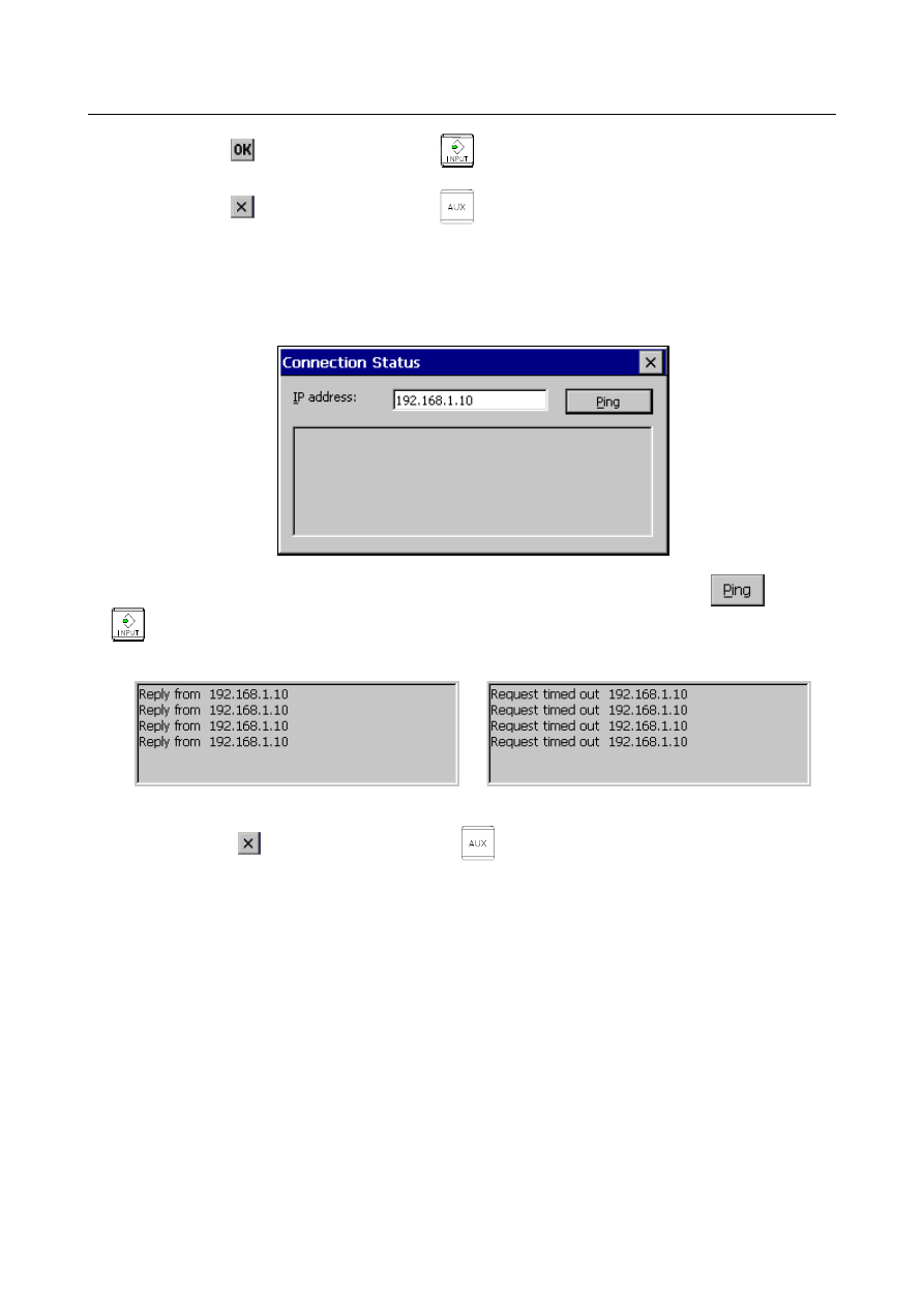
Response check of CNC to be connected 

Select the "Connection Status" in the "Settings & maintenance" menu, then the screen for the response 
check of CNC to be connected will be displayed. 


Input an IP address (Ex.: 192.168.1.10) of CNC to check its response, then press the 

  button or 


  key on the MDI keyboard. 

The checking by the PING command is run 4 times, and the result is displayed. 


The response is received.                          The response is not received. 


By pressing the 

  button on the screen or 


  key on the MDI keyboard, the "Settings & 

maintenance" menu comes back. 
 

B-64693EN-1/01


13. DISPLAY/SET/EDIT


- 2331 - 

  - 

Communication status with CNC


Select the "Communication Status" in the "Settings & maintenance" menu, then the screen for the 
communication status with CNC will be displayed. 


The communication with CNC is continued while displaying the screen and the data of communication 
status is updated. 
 
The displayed items are as follows: 

Item 

Description 

Baudrate 

Communication rate and mode. 
When the communication is not established, "------" is displayed. 

Send packets 

Number of send packets 

Send errors 

Number of send errors   

Receive packets 

Number of receive packets 

Receive errors 

Number of receive errors 

Frame alignment errors 

Number of frame alignment errors 

Collision errors 

Number of collision errors 

16 Collisions errors 

Number of 16 consecutive collision errors 

Overrun errors 

Number of overrun errors 


By pressing the 

  button on the screen or 


  key on the MDI keyboard, the "Settings & 

maintenance" menu comes back. 
 

13. DISPLAY/SET/EDIT


B-64693EN-1/01


- 2332 - 

  - 

Calibration of the touch panel 

Select the "Touch Panel Calibration" in the "Settings & maintenance" menu, then the calibration screen 
for the touch panel will be displayed. Follow the guidance messages shown in the screen. 


After the calibration is finished, the "Settings & maintenance" menu comes back. 
 

13.1.11 

Speed Display Function of a Milling Tool with Servo Motor 

Overview 

Any servo motor axis can be selected to display its speed considering gear ratio. 
 

Explanation 

The screen display can be switched between the speed of the milling axis and the spindle speed by using 
an input signal SDPC <Gn038.5>. 


Fig. 13.1.11 (a) 

(*) 

B-64693EN-1/01


13. DISPLAY/SET/EDIT


- 2333 - 


Fig. 13.1.11 (b) 


Fig. 13.1.11 (c) 


  - 

Switching to the display of the speed of a milling tool with a servo motor 

With the speed display change signal SDPC<Gn038.5>, the speed of a milling axis or the spindle speed 
can be selected and indicated in the part marked by (*) in the Fig. 13.1.11 (a) to Fig. 13.1.11 (c). 
 

  - 

Displaying the speed of a milling tool with a servo motor


As the speed of a milling axis, the value obtained by multiplying the servo motor speed by the gear ratio 
is indicated. 


1899)


No.


(parameter


side


axis


milling


on the


gear teeth


of

Number 

1898)


No.


(parameter


side


axis

motor 


servo


on the


gear teeth


of

Number 

ratio

Gear 

=


To select the target servo motor axis, set a controlled axis number as the number of a servo motor axis 
used as the axis of a milling tool (parameter No. 1895). 

  (*)


(*) 

13. DISPLAY/SET/EDIT


B-64693EN-1/01


- 2334 - 


NOTE 

1  If parameter Nos. 1898 and 1899 are not set, the gear ratio is assumed to be 

1:1. 

2  If an axis that uses a linear motor is selected, the speed cannot be displayed. 
3  Even when the speed of a milling axis is displayed, the actual speed of feed per 

revolution follows the speed of the spindle. 


Signal 

Speed display change signal SDPC<Gn038.5> 

  [Classification]  Input signal 
 

[Function]  Selects the speed to be displayed: the speed of the milling axis or the spindle speed.


[Operation]


If this signal is set to “1”, the speed of the milling axis is displayed. 
If this signal is set to “0”, the spindle speed is displayed. 


Signal address


#7 

#6 

#5 

#4 

#3 

#2 

#1 

#0 

Gn038 


SDPC 


Parameter 


#7 

#6 

#5 

#4 

#3 

#2 

#1 

#0 

3105 


DPS 


[Input type]  Parameter input 


[Data type]  Bit path 


#2  DPS

  The actual spindle speed is: 

0: 

Not displayed 

1: 

Displayed 


1895 


Servo motor axis number used for a milling tool 


[Input type]  Parameter input 


[Data type]  Byte path 

[Valid data range]  1 to number of controlled axes 

This parameter sets the servo motor axis number used for displaying the speed of a 
milling tool that incorporates a servo motor. 
 

1898 


Number of gear teeth on the servo motor axis side 


[Input type]  Parameter input 


[Data type]  Word axis 

[Valid data range]  1 to 9999 

This parameter sets the number of servo motor axis gear teeth used for displaying the 
speed of a milling tool that incorporates a servo motor. 
 

NOTE 


This parameter is valid when a non-zero value is set in parameter 
No. 1895. 


1899 


Number of gear teeth on the milling axis side 


B-64693EN-1/01


13. DISPLAY/SET/EDIT


- 2335 - 


[Input type]  Parameter input 


[Data type]  Word axis 

[Valid data range]  1 to 9999 

This parameter sets the number of milling axis gear teeth used for displaying the speed of 
a milling tool that incorporates a servo motor. 
 

NOTE 


This parameter is valid when a non-zero value is set in parameter 
No. 1895. 


13.1.12 

Screen Switching by Mode 

Overview 

One of the screens displayed using function key 


  such as the program edit screen and the program 

check screen can be selected according to the mode. When a mode switches to other mode, the screen 
selected last in that mode is displayed. 
 
There are five modes, and immediately after the power is turned on in each mode, a screen is selected as 
follows: 
MEM 

Program check screen (for MEM) 

EDIT 

Program edit screen (for EDIT) 

MDI  

Program edit screen (for MDI) 

TJOG/THND 

Program edit screen 

Other modes 

Program edit screen 


Mode switching and screen examples 

  - 

Mode switching after power-on 

When the MEM mode is selected and function key 


  is pressed at power-on, the program check 

screen is displayed.


When the mode is changed to the EDIT mode, the program edit screen is displayed.


  - 

Mode switching after screen operation 

When soft key [FOLDER] is pressed in the EDIT mode, the program list screen is displayed. 
When the mode is changed to the MEM mode, the program check screen is displayed. 
Then, when the mode is changed to the EDIT mode, the program list screen is displayed. 


MEM mode 


13. DISPLAY/SET/EDIT


B-64693EN-1/01


- 2336 - 


EDIT mode


B-64693EN-1/01


13. DISPLAY/SET/EDIT


- 2337 - 

  - 

Mode switching after screen operation


When soft key [FOLDER] is pressed in the EDIT mode, the program list screen is displayed. 
When the mode is changed to the MEM mode, the program check screen is displayed. 
Then, when the mode is changed to the EDIT mode, the program list screen is displayed. 


EDIT mode


MEM mode 


EDIT mode


Content      ..     295      296      297      298     ..