FANUC Series 0i-MODEL F Plus. CONNECTION MANUAL (FUNCTION) - page 256
11. TOOL FUNCTIONS
B-64693EN-1/01
- 2002 -
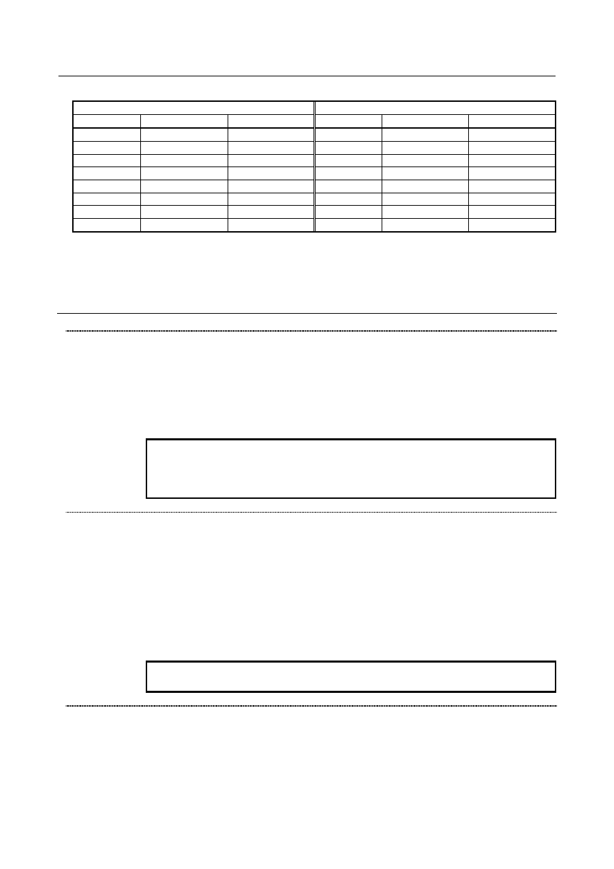
Table 11.4.4
First geometry tool offset
Second geometry tool offset
No.
X axis
Z axis
No.
X axis
Z axis
01
20.000
5.000
01
0.000
0.000
:
:
:
:
:
:
10
25.000
8.000
10
0.000
0.000
11
-20.000
5.000
11
120.000
10.000
12
-10.000
3.000
12
120.000
-30.000
13
-15.000
0.000
13
120.000
-70.000
:
:
:
:
:
:
16
-18.000
7.000
16
120.000
-190.000
-
Offset data
The data for the second geometry tool offset can be set for each path. The number of items of the data can
be set with parameter No. 5024. The data remains stored even after the power is turned off.
If the data is to be made common to paths, use the memory common to paths.
Signal
Second geometry tool offset signal G2SLC<Gn090.7>
[Classification] Input signal
[Function] This signal selects whether to use the second geometry tool offset.
[Operation] When a tool number is specified with a T code, only the first geometry tool offset is used
as the tool geometry offset value if this signal is 0; if this signal is 1, the value obtained
by adding the second geometry tool offset to the first geometry tool offset is used as the
tool geometry offset value.
NOTE
To switch this signal, use an M code for suppressing buffering. If
the signal is switched without suppressing buffering during
automatic operation, it is likely that no offset may work properly.
Second geometry tool offset axis selection signals
G2X,G2Z,G2Y<Gn090.4, Gn090.5, Gn090.6>
[Classification] Input signal
[Function] These signals select the axis for which the second geometry tool offset is added to the
first geometry tool offset.
[Operation] If these signals are set to 0, the second geometry tool offset is not added to the controlled
axis corresponding to the axis bit.
If these signals are set to 1, the second geometry tool offset is added to the controlled axis
corresponding to the axis bit.
These signals are valid when the second geometry tool offset signal G2SLC is set to 1.
NOTE
G2Y requires the Y-axis offset.
Tool offset direction signals G2RVX,G2RVZ,G2RVY<Gn090.0, Gn090.1, Gn090.2>
[Classification] Input signal
[Function] When a tool offset is used, these signals change the direction of the compensation
amount.
The direction of the tool offset for compensation is determined by tool movement as
follows:
0:
The same direction as the direction indicated by the sign