FANUC Series 0i-MODEL F Plus. CONNECTION MANUAL (FUNCTION) - page 257
 

  Index      Manuals     FANUC Series 0i-MODEL F Plus. CONNECTION MANUAL (FUNCTION) B-64693EN-1/01


Search            copyright infringement  


Content      ..     255      256      257      258     ..


FANUC Series 0i-MODEL F Plus. CONNECTION MANUAL (FUNCTION) - page 257


11. TOOL FUNCTIONS


B-64693EN-1/01


- 2010 - 

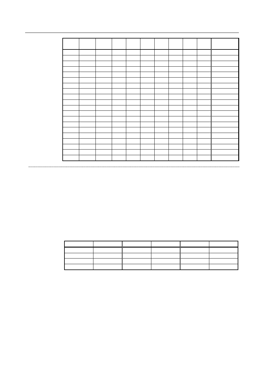
TL512 

TL256 

TL128 

TL64 

TL32 

TL16 

TL08 

TL04 

TL02 

TL01 

Tool group 

number 

30 

40 

50 

100 

127 

128 

200 

256 

257 

300 

400 

500 

512 

513 

600 

700 

800 

900 

1000 

1024 


Tool life count override signals *TLV0 to *TLV9 <Gn049.0 to Gn050.1> 

  [Classification]  Input signal 
 

[Function]  If the tool life count type  is specified by duration, the life count can be overridden by 

setting bit 2 (LFV) of parameter No. 6800 = 1. Ten binary code signals are available, and 
they correspond to override values as follows: 


Override value  =  


Σ

 {2i 

×

 Vi} 

times 

 
Keep the override values within the range stated above. 

Where, if *TLVi is 1, Vi = 0 
      if *TLVi is 0, Vi = 1 
Therefore, each signal has the following weight: 

Signal 

Magnification 

Signal 

Magnification 

Signal 

Magnification 

*TLV0 

0.1 

*TLV4 

1.6 

*TLV8 

25.6 

*TLV1 

0.2 

*TLV5 

3.2 

*TLV9 

51.2   

*TLV2 

0.4 

*TLV6 

6.4 

*TLV3 

0.8 

*TLV7 

12.8 


Example: 
 

If *TLV7, *TLV6,  and *TLV3 are 0, the override value is calculated as follows: 
12.8 + 6.4 + 0.8 = 20.0 
So, the life count is multiplied by 20. 


If all signals are 1, the override value is 0. So, set an override value within the range 
from 0 to 99.9 in steps of 0.1. 


If 99.9 times is exceeded, the actual override value is clamped by 99.9 times. 


[Operation]  The actual cutting time obtained by life counting specified by duration is multiplied by 

the override value specified by these signals, and the multiplication result is assumed to 
be the count time for tool life management. For example, let the override value be 0.1, 
and the actual cutting time be 1000 seconds. Then, the tool life count time is assumed to 
be 100 seconds. 


9


i=0


B-64693EN-1/01


11. TOOL FUNCTIONS


- 2011 - 

Tool life arrival notice signal TLCHB <Fn064.3> 

  [Classification]  Output signal 
 

[Function] If the tool life management B function is enabled (bit 4 (LFB) of parameter No. 6805 = 1), 

specifying a remaining life value to be used till selection of a new tool enables the tool 
life arrival notice signal to be  issued when life counting shows that the remaining life 
value of a group (life value minus life counter value) becomes lower than or equal to the 
remaining life setting, in order to inform in advance that the tool life will expire soon. 
By bit 4 (ARL) of parameter No. 6802, it is possible to select whether to output the tool 
life arrival notice signal for each tool or the last tool in the group. 
Bit 3 (GRP) of parameter No. 6802 can be used to specify which remaining life setting 
(that is, one specified in  parameter Nos. 6844 and 6855 or one registered as tool life 
management data) to use. 


[Output cond.]  The signal is set to 1 if: 

Remaining life (life value - life counter value) 

 remaining life setting 

provided that bit 7 (RMT) of parameter No. 6802 = 0 

Remaining life (life value - life counter value) =


remaining life setting 

provided that bit 7 (RMT) of parameter No. 6802 = 1 

The signal is reset to 

0 if

Remaining life (life value - life counter value) 

remaining life setting 

provided that bit 7 (RMT) of parameter No. 6802 = 0 

Remaining life (life value - life counter value) 


remaining life setting 

provided that bit 7 (RMT) of parameter No. 6802 = 1 


NOTE 

1  The signal changes when life counting is performed. 
2  When using a life count override, reset bit 7 (RMT) of parameter 

No. 6802 to 0. 

3  When the life count is specified by duration, the unit of the 

remaining life and remaining life setting to be compared varies 
depending on the life count interval (bit 0 (FCO) of parameter No. 
6805). If the tool life is counted every second, the unit of the values 
to be compared is one minute; if the tool life is counted every 0.1 
second, the unit of the values to be compared is 0.1 minute. 

 
If bit 7 (CTB) of parameter No. 6803 is 1, this signal can be set to 0 when an operation 
such as the following is performed. 

Clears the execution data on the list screen of tool life management. 

Deletes all tool group data at a time, adds a tool number, or deletes tool data on the 
edit screen of tool life management. 

Clears the execution data by the tool change reset signal TLRST <Gn048.7>. 

Registers, changes, or deletes all tool life management group data by the G10 
command. 

Executes the FOCAS2 cnc_clrcntinfo function (which clears the tool life counter or 
tool information). 

Replaces a tool with a tool of which life is not managed by the M06 command. 


Tool life counting disable signal LFCIV<Gn048.2> 

  [Classification]  Input signal 
 

[Function]  Disables tool life counting for selected tools. 


[Operation]  If the signal turns to 1, the control unit behaves as explained below. 

No life counting is performed for selected tools. 


11. TOOL FUNCTIONS


B-64693EN-1/01


- 2012 - 

NOTE 

The tool life counting disable signal LFCIV<Gn048.2> is valid if bit 
6 (LFI) of parameter No. 6804 is 1. 


Tool life counting disabled signal LFCIF<Fn093.2> 

  [Classification]  Output signal 
 

[Function]  Informs that tool life counting is disabled for selected tools. 


[Output cond.]  The signal becomes 1 when: 

Tool life counting is disabled because the tool life counting disable signal LFCIV is 

1. 

The signal becomes 0 when: 

Tool life counting is enabled because the tool life counting disable signal LFCIV is 

0


Number of remaining tools notification signal TLAL <Fn154.0> 

  [Classification]  Output signal 
 

[Function]  Informs that the number of remaining tools in the group selected with a T code command 

is equal to or less than the setting of parameter No. 6846. 


[Output cond.]  The signal becomes 1 when: 

The number of remaining tools in the group selected with a T code command is 
equal to or less than the setting of parameter No. 6846. 

 
The signal becomes 0 when: 

A value is input to parameter No. 6846. 

Using a G10 command, registration is performed that involves the erasure of all life 
management data groups. 

Using a T code command, a group is selected in which the number of remaining 
tools is greater than the setting of parameter No. 6846. 

 
The signal also becomes 0 when any of the following is executed in the group that has 
caused the number of remaining tools notification signal TLAL to be generated. 

Clearing of execution data, using the tool change reset signal TLRST <Gn048.7>. 

Change and deletion of life management data, using a G10 command. 

Batch deletion of tool groups from the group edit screen of tool life management, 
addition of tool data to the screen, and deletion from the screen. 

Clearing of tool execution data from the group edit screen of tool life management. 

Clearing of execution data from the list screen of tool life management. 

Execution of any of the FOCAS2 functions below. 


(cnc_clrcntinfo, cnc_deltlifegrp, cnc_deltlifedt, cnc_instlifedt, cnc_wrt1info, 


cnc_wrt2info, cnc_wr1tlifedata, cnc_wr1tlifedat2, cnc_wr2tlifedata) 


NOTE 

1  This signal is used in the M series only. 
2  If the setting of parameter No. 6846 is 0, the number of remaining 

tools notification signal TLAL is not output. 


Example) 
 

If three tools are registered in a group, and the number of remaining tools is set to 1 
(parameter No. 6846 = 1), the timing chart of the number of remaining tools 
notification signal TLAL is as shown in Fig. 11.5 (c). 


The number of remaining tools notification signal TLAL is output at the same time 
as the T code for the third tool. 

B-64693EN-1/01


11. TOOL FUNCTIONS


- 2013 - 


TF 

1st tool 

2nd tool 

3rd tool 

T-code 

TLAL 


Fig. 11.5 (c) Timing chart of the number of remaining tools notification signal TLAL 


Signal address 


#7 

#6 

#5 

#4 

#3 

#2 

#1 

#0 

G0046 


KEY4 

KEY3 

KEY2 

KEY1 


Gn047 


TL128 

TL64 

TL32 

TL16 

TL08 

TL04 

TL02 

TL01 


Gn048 


TLRST 

TLRSTI 

TLSKP 


LFCIV 

TL512 

TL256 


Gn049 


*TLV7 

*TLV6 

*TLV5 

*TLV4 

*TLV3 

*TLV2 

*TLV1 

*TLV0 


Gn050 


*TLV9 

*TLV8 


#7 

#6 

#5 

#4 

#3 

#2 

#1 

#0 

Fn064 


TLCHB 

TLCHI 

TLNW 

TLCH 


Fn093 


LFCIF 


Fn154 


TLAL 


Parameter 


#7 

#6 

#5 

#4 

#3 

#2 

#1 

#0 

6800 


M6T 

IGI 

SNG 

GRS 

SIG 

LTM 

GS2 

GS1 


[Input type]  Parameter input 


[Data type]  Bit path 


#0  GS1


#1


GS2

  For the maximum number of groups set in parameter No. 6813, up to four tools can be 

registered per group. The combination of the number of registrable groups and the 
number of tools per group can be changed by setting GS1 and GS2. 
 

GS2  GS1 

Number of groups 

Number of tools 

1/8 of maximum number of groups (No. 6813) 

32 

1/4 of maximum number of groups (No. 6813) 

16 

1/2 of maximum number of groups (No. 6813) 

Maximum number of groups (No. 6813) 


11. TOOL FUNCTIONS


B-64693EN-1/01


- 2014 - 

NOTE 


After changing these parameters, set data again by using G10 
L3 ;(registration with deleting data of all groups). 


#2  LTM

  The tool life count type is specified by: 

0: 

Count. 

1: 

Duration. 


NOTE 


After changing this parameter, set data again by using G10 
L3 ;(registration after deletion of data of all groups). 


#3  SIG

  In tool skip by signals, the group number is: 

0: 

Not input by the tool group number selection signals  TL01

TL512<Gn047.0 


Gn048.1>. 

1: 

Input by the tool group number selection signals. 


NOTE 


When this parameter is set to 0, a tool of the currently used group is 
skipped. 


#4  GRS

  When the tool change reset signal TLRST <Gn048.7> is input: 

0: 

If the life of the group specified by the tool group number selection signals TL01 to 
TL512 <Gn047.0 to Gn048.1>  has expired, the execution data of the group is 
cleared. 

1: 

The execution data of all registered groups is cleared. 

If this parameter is set to 1, the execution data of all registered groups are  cleared also 
when the clear operation to clear execution data is performed on the tool life management 
list screen. 


#5  SNG

  When the tool skip signal TLSKP <Gn048.5> is input while a tool not controlled by the 

tool life management function is being used: 
0: 

A tool of the most recently used group or a specified group (bit 3 (SIG) of parameter 
No. 6800) is skipped. 

1: 

The tool skip signal is ignored. 


#6  IGI

  Tool back numbers are: 

0: 

Not ignored. 

1: 

Ignored. 


#7  M6T

  A T code specified in the same block as M06 is: 

0: 

Assumed to be a back number. 

1: 

Assumed to be a command specifying the next tool group. 


#7 

#6 

#5 

#4 

#3 

#2 

#1 

#0 

6801 


M6E 


EMD 

LVF 

TSM 


M6E 


EMD 

LVF 


NOTE 


The use of this parameter varies depending on whether the tool 
management function or tool life management function is used. 


[Input type]  Parameter input 

B-64693EN-1/01


11. TOOL FUNCTIONS


- 2015 - 


[Data type]  Bit path 


#1  TSM

  In the tool life management function, life counting is performed as follows when more 

than one offset is specified: 
0: 

Counting is performed for each tool number. 

1: 

Counting is performed for each tool. 


#2  LVF

  When the life value is counted by duration in the tool management function or tool life 

management function, tool life count override signals *TLV0 to *TLV9 <Gn049.0 to 
Gn050.1> are: 
0: 

Not used. 

1: 

Used. 


#3  EMD

  In the tool life management function, the mark "*" indicating that the life has expired is 

displayed when: 
0: 

The next tool is used. 

1: 

The life has just expired. 


NOTE 

If this parameter is set to 0, the "@" mark (indicating that the tool is 
in use) is kept displayed unless the next tool whose life has not 
expired is used. If this parameter is set to 1, marks are displayed in 
different ways depending on the life count type. 


If the life count type is the duration specification type, the "*" mark 
(indicating that the life has expired) appears when the life has 
expired. If the life count type is the count specification type, one 
count is not assumed until the end of the program (M02, M30, and so 
on). Therefore, even when the life value and the tool life counter 
value match, the "*" mark (life has expired) does not appear. The "*" 
mark (life has expired) appears when the tool is used again by a tool 
group command (T code) or tool change command (M06) issued 
after the CNC is reset. 


#7  M6E

  When a T code is specified in the same block as M06: 

0: 

The T code is treated as a back number or the group number to be selected next. 


Which number is assumed depends on the setting of bit 7 (M6T) of parameter No. 
6800. 

1: 

Life counting for the tool group starts immediately. 


#7 

#6 

#5 

#4 

#3 

#2 

#1 

#0 

6802 


RMT 

TSK 

TGN 

ARL 

GRP 

E17 

TCO 

T99 


[Input type]  Parameter input 


[Data type]  Bit path 


#0  T99

  When M99 of the main program is executed, and if there is a tool group whose life is 

expired: 
0: 

The tool change signal is not output. 

1: 

The tool change signal is output and the automatic operation stop state is entered.. 

 
If the life count is specified by use count and this parameter 1, the tool change signal 
TLCH <Fn064.0> is output and the automatic operation becomes a stopped state if there 
is a tool group whose life is expired when the M99 command is specified. 

11. TOOL FUNCTIONS


B-64693EN-1/01


- 2016 - 

If the life count type is the duration specification type, the automatic operation becomes a 
stopped state if the life of at least one tool group has expired. 

M


If the life count is specified by use count, after the M99 command is specified, a tool 
group command (T code) selects, from a specified group, a tool whose life has not 
expired, and the next tool change command (M06) increments the tool life counter by 
one. 
 

T


If the life count is specified by use count, when a tool group command (T code) is 
specified after the M99 command is specified, a tool whose life has not expired is 
selected from a specified group, and the tool life counter is incremented by one.   
When the tool change type is the ATC type (bit 3 (TCT) of parameter No. 5040 = 1), the 
same specifications as for the M series apply.   


#1  TCO   


#2  E17 

Specifies whether to allow the FOCAS2 or PMC window function to write tool 
information of a group being used or a group to be used next during automatic operation 
(the automatic operation signal OP <Fn000.7> is set to 1). 
 

Condition 

Bit 1 (TCO) of parameter 

No. 6802 

Bit 2 (E17) of 

parameter No. 6802 

During 

automatic 

operation 

Group being used or to be 

used next 

Tool being used 

× 


○ 

Tool not being used 

× 

○ 

○ 

Group neither being used nor to be used next 

○ 

○ 

○ 

Not during automatic operation 

○ 

○ 

○ 

○:  Tool information can be written from FOCAS2 and PMC window. 
×: 

Tool information cannot be written from FOCAS2 and PMC window. 


When an attempt is made to write tool information from PMC window, completion 
code 13 (REJECT ALARM) is returned. 

:  Tool information cannot be cleared. 


NOTE 

When tool information of a tool being used (marked with "@") in the 
group being used or to be used next or tool information of the most 
recently used tool (marked with "@") in a group that is neither the 
group being used nor the group to be used next is cleared, the life 
counter is reset to 0. 
It is possible to modify tool information of a tool in the group to be 
used next. However, because tool selection is already completed, 
the selected tool does not change even when the tool information is 
modified. 


This parameter has no influence on modifications to tool information 
by edit operations from the tool life management screen. 


#3  GRP

  Management data of tool life arrival notice signal TLCHB <Fn064.3> is: 

0: 

Managed using the remaining life value set in parameter No. 6844 and 6845. 

1: 

Managed using the remaining life value set in tool life management data. 

B-64693EN-1/01


11. TOOL FUNCTIONS


- 2017 - 


NOTE 


When the tool life arrival notice signal function is used, bit 4 (LFB) of 
parameter No. 6805 must be set to 1 to enable the tool life 
management B function. 


#4  ARL

  Tool life arrival notice signal TLCHB <Fn064.3> of tool life management is: 

0: 

Output for each tool. 

1: 

Output for the last tool of a group. 

This parameter is valid only when bit 3 (GRP) of parameter No. 6802 is set to 1. 


#5  TGN

  In the tool life management function, the optional group number function is: 

0: 

Not used. 

1: 

Used. 


NOTE 

When the optional group number function is used, bit 4 (LFB) of 
parameter No. 6805 must be set to 1 to enable the tool life 
management B function. 


In lathe systems, the optional group number function can be used if 
the tool change type is the ATC type (bit 3 (TCT) of parameter No. 
5040 = 1). 


#6  TSK

  If the count type in tool life management is the duration type, then when the last tool of a 

group is skipped by a signal: 
0: 

The count value for the last tool equals the life value. 

1: 

The count value for the last tool remains unchanged. 


#7  RMT

  Tool life arrival notice signal TLCHB <Fn064.3> is turned 1 and 0 as follows: 

0: 

The signal is turned 1  if the remaining life value (the life value minus the life 
counter value) is smaller than or equal to the remaining life setting. The signal is 
turned  0  if the remaining life value (the life value minus the life counter value) is 
greater than the remaining life setting. 

1: 

The signal is turned 1  if the remaining life value (the life value minus the life 
counter value) is equal to the remaining life setting. The signal is turned 0  if the 
remaining life value (the life value minus the life counter value) is not equal to the 
remaining life setting. 


NOTE 


When using the life count override feature, set bit 7 (RMT) of 
parameter No. 6802 to 0. When the life count is specified by duration, 
the unit used for determining the result of comparison between the 
remaining life and the remaining life setting varies depending on the 
life count interval (bit 0 (FCO) of parameter No. 6805). If the life is 
counted every second, the comparison is made in units of 1 minute; if 
the life is counted every 0.1 second, the comparison is made in units 
of 0.1 minute. 


#7 

#6 

#5 

#4 

#3 

#2 

#1 

#0 

6803 


CTB 


[Input type]  Parameter input 


Content      ..     255      256      257      258     ..