FANUC Series 0i-MODEL F Plus. CONNECTION MANUAL (FUNCTION) - page 217
 

  Index      Manuals     FANUC Series 0i-MODEL F Plus. CONNECTION MANUAL (FUNCTION) B-64693EN-1/01


Search            copyright infringement  


Content      ..     215      216      217      218     ..


FANUC Series 0i-MODEL F Plus. CONNECTION MANUAL (FUNCTION) - page 217


10. SPINDLE SPEED FUNCTION


B-64693EN-1/01


- 1690 - 

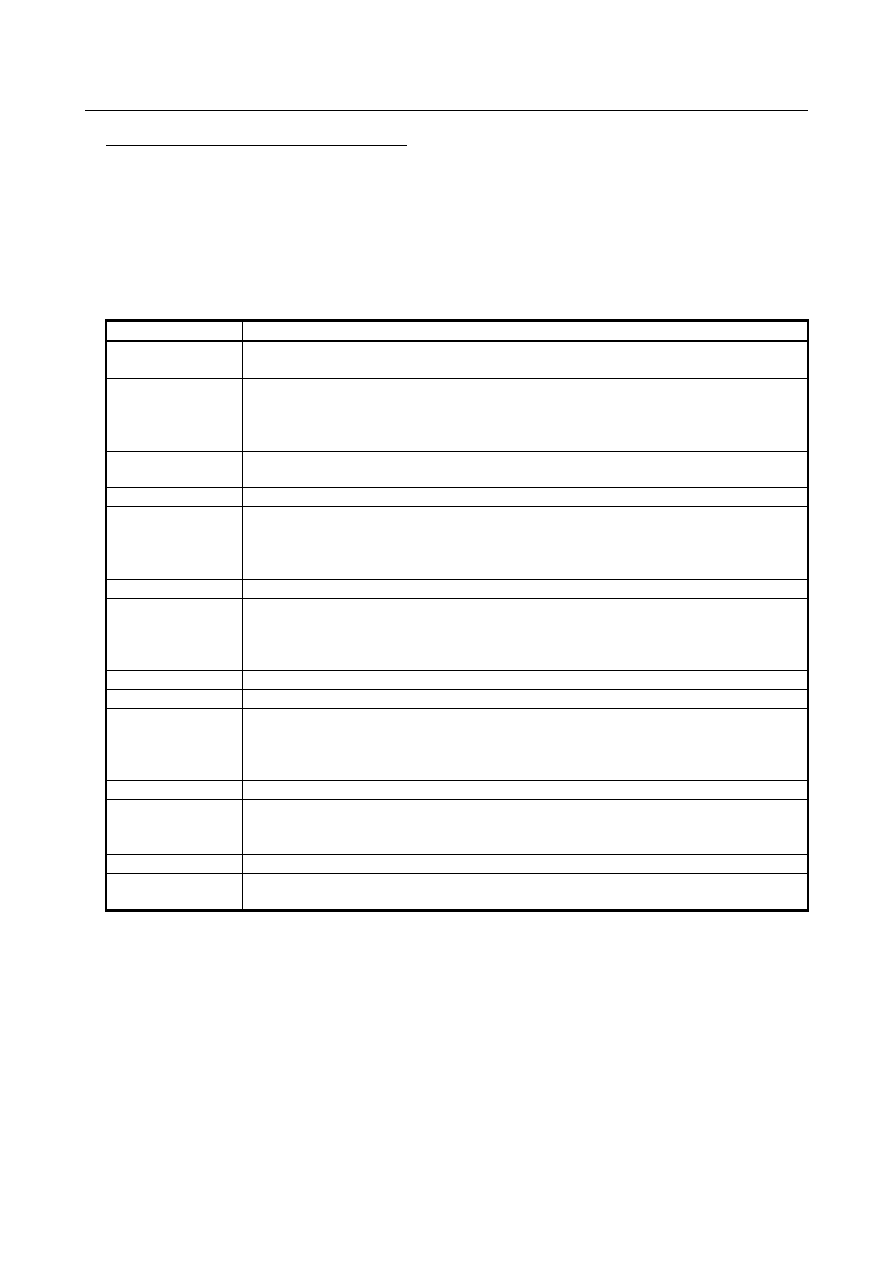
Parameter list related to Normal rigid tapping 
 

In case of the retraction of rigid tapping after the breakage of tool on cutting by Smart rigid tapping, 
Normal rigid tapping is necessary even if Smart rigid tapping. To use Normal rigid tapping, the 
setting of time constant parameter for acc./dec. is required. The following list shows the tuning 
parameter for Normal rigid tapping. In case that the tuning for Normal rigid tapping has finished, it’s 
not necessary to change these parameters. Regarding the detail of each parameter, refer to the 
chapter of "Parameter" in this manual or the chapter of "Rigid tapping" in FANUC AC SPINDLE 
MOTOR 

a

i

/

β

i

 series BUILT-IN SPINDLE MOTOR B

i

 series parameter manual (B-65280EN). 


Table 10.13.17 (e)    Parameter list related to Normal rigid tapping 

Parameter No. 

Contents 

5280 
5281 to 5284 

Position gain of tapping axis at rigid tapping 
(No. 5284 is used for the T series only.) 

5261 
5262 
5263 
5264 

Acc/Dec time constant 
(No. 5264 is used for the T series only.) 

5201#2 
5271 to 5274 

Time constant for acceleration/deceleration in rigid tapping extraction (No. 5274 is used for 
the T series only.) 

5203#2 

Feed-forward function at rigid tapping 

5310 
5350 
5354 
5358 

Allowable level of position error of tapping axis at moving 

5311 

Allowable level of position error of spindle at moving 

5312 
5352 
5356 
5360 

Allowable level of position error of tapping axis at stop 

5313 

Allowable level of position error of spindle at stop 

5203#5 

Selection of bell shape acc./dec. for rigid tapping 

5365 
5366 
5367 
5368 

Bell shape acc./ dec. time constant for rigid tapping 
(No. 5368 is used for the T series only.) 

4037 

Velocity loop feed-forward coefficient 

4344 

Advanced preview feed-forward coefficient 
(This parameter sets the coefficient for rapid traverse when bit 4 of parameter No. 4542 is 
1.) 

4542#4 

Cutting feed/rapid traverse feed-forward function 

4627 

Advanced preview feed-forward coefficient for cutting feed 
(This parameter is valid when bit 4 of parameter No. 4542 is 1.) 


Restriction 

If you use rough TTL resolution sensor such as 

a

i

 Positioncoder(4096pulse/rev) in spindle position 

sensor, there is a possibility that the vibration or strange sound might be detected due to the 
following movement of servo axis to rough feedback data. We don’t recommend to use such sensors 
for Smart rigid tapping. Use analog 1Vpp sensor or serial type sensor. 


You can’t use Smart rigid tapping in the following conditions. 

Using sensor-less motors as spindle motor 

Using Spindle differential speed control 


B-64693EN-1/01


10. SPINDLE SPEED FUNCTION


- 1691 - 

Smart rigid tapping becomes invalid in the following kinds of rigid tappings. In these cases, Normal 
rigid tapping will be executed. When you use them, set some parameters such as time constant 
which are shown in "Parameter list related to Normal rigid tapping". 

Peck rigid tapping 

Rigid tapping by manual handling feed 

Extraction in rigid tapping 

Rigid tapping using Spindle control by servo motor 

Rigid tapping by analog spindle 


In the situation that plural spindle axes are synchronized by Spindle command synchronous control 
mode, Smart rigid tapping becomes invalid. PS0203 alarm "PROGRAM MISS AT RIGID 
TAPPING" will occur. 


Smart rigid tapping becomes invalid in the checking mode in manual handle retrace. In the mode, 
Normal rigid tapping will be executed. 


As Smart rigid tapping executes acc./dec. by spindle maximum power, Acc./dec. after interpolation 
and Look-ahead acc./dec. before interpolation become invalid. 


In Smart rigid tapping over-ride signals for feed axes *FV0-*FV7<Gn012>  and over-ride cancel 
signal OVC<Gn006.4> become invalid even if parameter OVS(No.5203#4)=1. Over-ride for 
extraction of rigid tapping is valid. 


In Smart rigid tapping the backlash compensation for spindle becomes invalid. The backlash 
compensation for feed axis becomes valid. 


Interlock and machine lock become invalid during smart rigid tapping. Axes become interlock state 
or machine lock state after finishing Smart rigid tapping. 


In Smart rigid tapping feed hold and single block become invalid. The axes don’t stop until the end 
of 1cycle of tapping. 


Reset and emergency stop during Smart rigid tapping make velocity command 0 stop. 


It’s impossible to change feedrate by external deceleration during Smart rigid tapping. Feedrate at 
starting cutting or extraction is maintained. 


The following functions become invalid during Smart rigid tapping. 

General purpose retract 

Tool retract and recover 

One-digit F code feed 

Manual handle interrupt 


When you use 3-dimensional rigid tapping, set D3R (Parameter No.11221#1) to “1”. 


The following settings are not supported for Smart rigid tapping axis. 

Slave axis of superimposed control 

Slave axis of flexible synchronization control 

Slave axis of electronic gear box 


Alarm (SV0048) "SMART RIGID TAPPING STOP" will occur with the following alarms during 
Smart rigid tapping and the excitation of servo motor will be turned off. Alarm (SV0048) can be 
canceled with reset. 

Alarm (SP9xxx) (when spindle motor is deactivated) 

10. SPINDLE SPEED FUNCTION


B-64693EN-1/01


- 1692 - 

Alarm (SP0741) (when  synchronous error range exceeds the setting value of parameter 
(No.5214)) 


When SRT(No.5206#1) is 1 and the spindle software, which doesn’t support Smart rigid tapping, is 
used, alarm PS0564 "ILLEGAL COMMAND OF SMART RTAP" will occur at rigid tapping. 


10.13.18 

Parameter 


#7 

#6 

#5 

#4 

#3 

#2 

#1 

#0 

2005 


FEED 


[Input type]  Parameter input 


[Data type]  Bit axis 


#1  FEED

  Feed forward function is: 

0: 

Disabled. 

1: 

Enabled. 


NOTE 


Set 1 to the synchronizing servo axis with spindle axis on FSSB 
high-speed rigid tapping. 


In FSSB high-speed rigid tapping mode, the feed forward 
coefficient becomes 100 percent. 


NOTE 


This parameter is initial setting parameter. For details, refer to the 
appendix "Automatic setting / Initial setting parameter" in 
CONNECTION MANUAL (FUNCTION) (B-64693EN-1). 


#7 

#6 

#5 

#4 

#3 

#2 

#1 

#0 

2423 


RGDBLA 


[Input type]  Parameter input 


[Data type]  Bit axis 


#2  RGDBLA

  Setting for the compensation of reverse operation in Smart rigid tapping 

0: 

Compensation invalid 

1: 

Compensation valid 


#7 

#6 

#5 

#4 

#3 

#2 

#1 

#0 

2429 


FHRSV 


[Input type]  Parameter input 


[Data type]  Bit axis 


#1  FHRSV

  Servo axis control of FSSB high-speed rigid tapping is: 

0: 

Disabled. 

1: 

Enabled. 


NOTE 


Set 1 to the synchronizing servo axis of a spindle axis on FSSB 
high-speed rigid tapping. 


B-64693EN-1/01


10. SPINDLE SPEED FUNCTION


- 1693 - 

2610 


Position control loop gain for the tapping axis in FSSB high-speed rigid tapping 


[Input type]  Parameter input 


[Data type]  Word axis 

[Valid data range]  0 to 32767 


The position control loop gain for the tapping axis (servo axis) in FSSB high-speed rigid 
tapping can be set. 
If the setting value of this parameter is 0, the position control loop gain is the same as the   
position gain (parameters Nos.5280 to 5284) of conventional rigid tapping used by both 
of servo axis and spindle axis. 


2611 


Coefficient of velocity feed-forward for feed axis in smart rigid tapping 


[Input type]  Parameter input 


[Data type]  Word axis 


[Unit of data]  1% 

 [Standard setting]  0 

Use this parameter to improve the axis response in case that the synchronous error is large 
at the start point of tapping as follow figure. Increase this value to every 100 with 
watching the synchronous error. There is a possibility that the torque command of servo 
axis might become vibrating at acc./dec. if the value is too large. 
 

主軸速度

主軸トルクコマンド

同期誤差

No.2611=0

No.2611=350


2613 


Compensation of reverse operation in Smart rigid tapping 


[Input type]  Parameter input 


[Data type]  Word axis 


[Unit of data]  0.01% 

[Valid data range]  0 to 10000 
 [Standard setting]  0 

Use this parameter to improve the axis response in case that the synchronous error 
becomes large at the reversal point of tapping. Please increase this value to every 100 
with watching the synchronous error. 
 

同期誤差

主軸速度

No.2613=0

No.2613=700


Synchronous error 

Spindle speed 

Spindle torque command 

Synchronous error 

Spindle speed 

10. SPINDLE SPEED FUNCTION


B-64693EN-1/01


- 1694 - 


#7 

#6 

#5 

#4 

#3 

#2 

#1 

#0 

3702 


EMS 


[Input type]  Parameter input 


[Data type]  Bit path 


#1  EMS

  The multi-spindle control is: 

0: 

Used. 

1: 

Not used.   


#7 

#6 

#5 

#4 

#3 

#2 

#1 

#0 

3703 


SPR 

MPP 

MPM 


2P2 


[Input type]  Parameter input 


[Data type]  Bit 


NOTE 


When at least one of these parameters is set, the power must be 
turned off before operation is continued. 


#0  2P2

  When a multi-path system is used, inter-path spindle control allows: 

0: 

Configuration where the spindle that belongs to one path only is shared between 
path 1 and path 2. 

1: 

Configuration where the spindles that belong to path 1 and 2 are shared between the 
two paths.   

When the spindle that belongs to an arbitrary path is shared between arbitrary paths, set 
bit 2 (MPM) of parameter No. 3703. (The meanings of signals used vary, so that ladder 
program modifications need to be made.) 


#2  MPM

  When a multi-path system is used, the configuration allowed by inter-path spindle 

control: 
0: 

Follows the setting of bit 0 (2P2) of parameter No. 3703. 

1: 

Allows the sharing of the spindle that belongs to a path between arbitrary paths. 


#3  MPP

  In multi-spindle control, a spindle selection using a programmed command instead of 

using the signals (SWS1 to SWS4<Gn027.0 to 2, Gn026.3>) is: 
0: 

Not made. 

1: 

Made. 


NOTE 


When this parameter is set to 1, set parameter No. 3781 at the same 
time. 


#4  SPR

  Rigid tapping with spindle of another path function is: 

0: 

Not available. 

1: 

Available. 

The  "rigid  tapping with spindle of another path" function can be combined with the 
address P-based spindle select function. This combination enables program commands (P 
code) to be used to select a spindle in a path other than the command issuing path for 
rigid tapping. 


B-64693EN-1/01


10. SPINDLE SPEED FUNCTION


- 1695 - 


#7 

#6 

#5 

#4 

#3 

#2 

#1 

#0 

3705 


EVS 

SGT 


ESF 


SFA 

NSF 


SGT 


ESF 


[Input type]  Parameter input 


[Data type]  Bit path 


#0  ESF

 When the spindle control function (Spindle analog output or Spindle serial output) is used, 

and the constant surface speed control function is used or bit 4 (GTT) of parameter No. 
3706 is set to 1:     
0: 

S codes and SF are output for all S commands.   

1: 

For the lathe system: 
 

S codes and SF are not output for an S command in the constant surface speed 
control (G96) mode and a command for maximum spindle speed clamping 
(G92 S_; (G50 for G code system A)). 


For the machining center system: 
 

S codes and SF are not output for an S command in the constant surface speed 
control (G96) mode. 


NOTE 


The operation of this parameter varies between the lathe system 
and machining center system. 
For the lathe system:   

This parameter is valid when bit 4 (EVS) of parameter No. 3705 
is set to 1. 

For the machining center system:   

For an S command for maximum spindle speed clamping   
(G92 S_;), SF is not output, regardless of the setting of this 
parameter. 


#3  SGT

  Gear switching method during tapping cycle (G84 and G74) is: 

0: 

Method A (Same as the normal gear switching method) 

1: 

Method B (Gears are switched during tapping cycle according to the spindle speed 
set in parameters Nos. 3761 and 3762).   


#4  EVS

 When the spindle control function (Spindle analog output or Spindle serial output) is used, 

S codes and SF are: 
0: 

Not output for an S command.   

1: 

Output for an S command.   

The output of S codes and SF for an S command in constant surface speed control mode 
(G96), or for an S command used to specify maximum spindle speed clamping (G92 S_; 
(G50 for G code system A)) depends on the setting of bit 0 (ESF) of parameter No. 3705. 


#5  NSF

  For the M series, when a T type gear is selected (with bit 4 (GTT) of parameter No. 3706 

set to 1 or constant surface speed control is enabled (bit 0 (SSC) of parameter No. 8133 is 
1)), and an S code is specified: 
0: 

SF is output. 

1: 

SF is not output. 


NOTE 


This parameter does not affect S code output. For an S command 
for maximum spindle speed clamping (G92 S_;), SF is not output, 
regardless of the setting of this parameter. 

10. SPINDLE SPEED FUNCTION


B-64693EN-1/01


- 1696 - 


#6  SFA

  The SF signal is output: 

0: 

When gears are switched. 

1: 

Irrespective of whether gears are switched. 


#7 

#6 

#5 

#4 

#3 

#2 

#1 

#0 

3706 


GTT 


[Input type]  Parameter input 


[Data type]  Bit path 


#4  GTT

  Spindle gear selection method is: 

0: 

M type. 

1: 

T type. 


NOTE 

1    This parameter is effected for M system. 
2  M type 
 

The gear selection signal is not input. The CNC selects a gear 
based on the speed range of each gear set by a parameter 
beforehand according to S codes, and the selected gear is posted 
by outputting the gear selection signal. Moreover, the spindle 
speed matching the gear selected by the output gear selection 
signal is output. 


T type 


The gear selection signal is input. The spindle speed matching the 
gear selected by this signal is output. 

3  When the constant surface speed control is enabled (bit 0 (SSC) of 

parameter No. 8133 is 1),    T type    is selected, regardless of 
whether this parameter is specified.   

4  When T type spindle gear switching is selected, the following 

parameters have no effect: 
No.3705#2(SGB), No.3751, No.3752,   
No.3705#1(GST), No.3705#3(SGT), No.3761, No.3762, 
No.3705#6(SFA), No.3735, No.3736 
On the other hand, parameter No. 3744 becomes usable. 

5  When multi spindle control is used, select to T type. 


3720 


Number of position coder pulses 


NOTE 


When this parameter is set, the power must be turned off before 
operation is continued. 


[Input type]  Parameter input 


[Data type]  2-word spindle 


[Unit of data]  Detection unit 

[Valid data range]  1 to 32767 

Set the number of position coder pulses. 
 

3761 


Spindle speed when switching from gear 1 to gear 2 during tapping 


B-64693EN-1/01


10. SPINDLE SPEED FUNCTION


- 1697 - 

3762 


Spindle speed when switching from gear 2 to gear 3 during tapping 


[Input type]  Parameter input 


[Data type]  2-word path 


[Unit of data]  min

-1


[Valid data range]  0 to 99999999 

When method B is selected as the gear change method in the tapping cycle (when bit 3 
(SGT) of parameter No. 3705 is set to 1), set the spindle speed at a change point of each 
gear. 


Spindle motor max. clamp speed   
(Parameter No.3736) 

Spindle speed 
command   
(S command) 

Max. speed (4095, 10V) 

Spindle motor minimum clamp speed   
(Parameter No.3735) 

Spindle motor speed 

Gear 1-2   
change point   
parameter   
No.3761 
 

Gear 2-3 
change point   
parameter   
No.3762 
 

Gear 1 
Max. speed   
Parameter 
No.3741 

Gear 2 
Max. speed   
Parameter 
No.3742 

Gear 3 
Max. speed   
Parameter 
No.3743 


#7 

#6 

#5 

#4 

#3 

#2 

#1 

#0 

4000 


RETSV 


[Input type]  Parameter input 


[Data type]  Bit spindle 


#4  RETSV

  Reference position return direction in the servo mode (rigid tapping, etc.) 

0: 

The spindle returns to the reference position counterclockwise (CCW). 

1:    The spindle returns to the reference position clockwise (CW). 
 

NOTE 


This parameter is valid only when a serial spindle is used. 


4073 


Grid shift amount in the servo mode 


[Input type]  Parameter input 


[Data type]  Word spindle 


Content      ..     215      216      217      218     ..