FANUC Series 0i-MODEL F Plus. CONNECTION MANUAL (FUNCTION) - page 215
 

  Index      Manuals     FANUC Series 0i-MODEL F Plus. CONNECTION MANUAL (FUNCTION) B-64693EN-1/01


Search            copyright infringement  


Content      ..     213      214      215      216     ..


FANUC Series 0i-MODEL F Plus. CONNECTION MANUAL (FUNCTION) - page 215


10. SPINDLE SPEED FUNCTION


B-64693EN-1/01


- 1674 - 


NC command 


Motion of servo 

axis 

RTAP 


S code output 


SF 


M code output 


MF 


FIN 


*SSTP 


SOR 


GR1/GR2 


SFR/SRV 


RGTAP 


ENB 


Spindle output 


Spindle rotation 


Position loop 

G84/G88 M29 

Motion 1 

Motion 2 

M29 

Gear select 

SFR=1 
SRV=0 

SFR=0 
SRV=0 

Spindle stop 

Gear change 

250ms   
or more* 

To be masked to the motion 2 


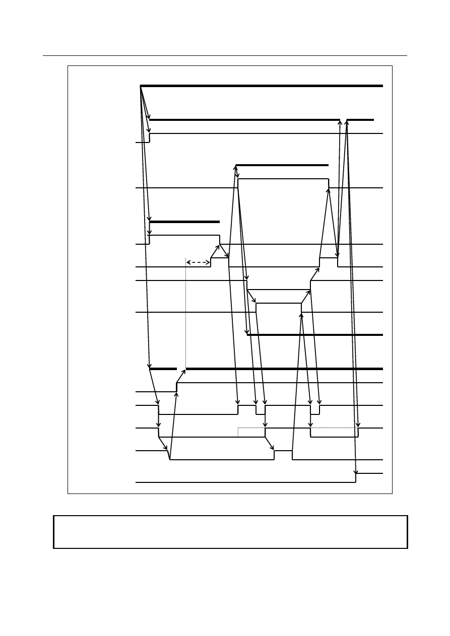
Fig. 10.13.15.5 (b) When gear-change is performed 


NOTE 


The delay(*) is not necessary, when an appropriate value is set to the parameter 
No.4099 for the delay time for stable motor excitation. 


B-64693EN-1/01


10. SPINDLE SPEED FUNCTION


- 1675 - 

10.13.15.6 

Specifying G84/G88 for rigid tapping by parameters 


NC command 


Motion of servo 

axis 

RTAP 


S code output 


SF 


M code output 


MF 


FIN 


*SSTP 


SOR 


GR1/GR2 


SFR/SRV 


RGTAP 


ENB 


Spindle output 


Spindle rotation 


Position loop 

G84/G88 

Motion 1 

Motion 2 

M29 is commanded 
internally. 

C axis clamp 

SFR=1 
SRV=0 

SFR=0 
SRV=0 

Spindle stop 

250ms 
or more* 

To be masked to the motion 2 


Fig. 10.13.15.6 (a) When gear-change is not performed 


NOTE 


The delay(*) is not necessary, when an appropriate value is set to the parameter 
No.4099 for the delay time for stable motor excitation. 


10. SPINDLE SPEED FUNCTION


B-64693EN-1/01


- 1676 - 


NC command 


Motion of servo 

axis 

RTAP 


S code output 


SF 


M code output 


MF 


FIN 


*SSTP 


SOR 


GR1/GR2 


SFR/SRV 


RGTAP 


ENB 


Spindle output 


Spindle rotation 

Position   

loop 

Motion 1 

Motion 2 

G84/G88 

M29 is commanded 

internally. 
 

C axis clamp 

Gear select 

SFR=1 
SRV=0 

SFR=0 
SRV=0 

Spindle stop 

Gear change 

250ms   
or more* 

To be masked to the motion 2 


Fig. 10.13.15.6 (b) When gear-change is performed 


NOTE 


The delay(*) is not necessary, when an appropriate value is set to the parameter 
No.4099 for the delay time for stable motor excitation. 


B-64693EN-1/01


10. SPINDLE SPEED FUNCTION


- 1677 - 

10.13.15.7 

Timing of the M code for unclamping 

T


After extraction from the hole bottom to the R point level (motion 5), the M code for unclamping is 
output. When FIN is returned, dwell or rapid traverse to the initial level (motion 6) starts. 


Motion 


M code output 


MF 


FIN 

Motion 5 

Dwell or motion 6 

C axis unclamp 


10.13.15.8 

Timing to cancel rigid tapping mode 

When rigid tapping is completed, the mode is canceled if a G code (such as G80, canned cycle G code, or 
Group 01 G code) is issued. 
Spindle output has the effect of execution of S0. On the falling edge of the ENB signal (corresponding 
ENBs signal in multi-spindle control), cancel the rigid tapping mode of the PMC (for example, by turning 
off spindle activation) and set the rigid tapping signal to "0". After confirming that the rigid tapping 
signal is set to "0", proceed to the next block. 
When gear change is performed using *SSTP and SOR, the ENB signal can be either "1" or "0". Do not 
cancel the PMC's rigid tapping mode at the falling edge of the ENB signal under these circumstances. The 
position loop is also canceled. 
When the CNC is reset, the PMC's rigid tapping mode must be canceled. 
When bit 2 (CRG) of parameter No. 5200 is 1, the system goes directly to the next block without 
checking that the rigid tapping signal is "0". Set CRG to 1 for systems in which the rigid tapping signal is 
always "1". 


NC command 


Servo axis 

operation 


RTAP 


SFR/SRV 


RGTAP 


ENBs 


Spindle output 


Position loop 

G80 

or G code of group 01 

Operation specified by cancellation 
block 

SFR=0 
SRV=0 


10. SPINDLE SPEED FUNCTION


B-64693EN-1/01


- 1678 - 

  CAUTION 

1  If rigid tapping mode is canceled by a Group 01 G code, such as G00 or G01, 

the block containing the G code is executed at the same time the ENB signal is 
turned to "0". Therefore, if the block contains an M code for controlling the 
spindle, an error may occur during processing in the PMC. 

2  When bit 2 (CRG) of parameter No. 5200 is 1, if the next block contains an M 

code for controlling the spindle, an error may occur during processing in the 
PMC, when:   

-  Rigid tapping mode is canceled by issuing G80 
-  Rigid tapping mode is canceled by issuing a Group 01 G code , such as G00 

or G01 


NOTE 


Rigid tapping mode is canceled as described above regardless of the gear 
selection method of M-type or T-type. 


10.13.16 

FSSB High-speed Rigid Tapping 

Outline 

By the FSSB communication between a CNC and a spindle amplifier, rotational position information of a 
spindle can be transmitted from a spindle amplifier to a servo control on CNC. The FSSB high-speed 
rigid tapping is a new function that a servo axis follows a spindle axis by utilizing this FSSB 
communication. And it is a characteristic of this function that the synchronization error becomes better 
than the ordinary function. And a synchronous error does not become worse even if a spindle error 
becomes worse by setting a shorter time constant for acceleration/deceleration than that of the former 
rigid tapping function. Therefore the machining cycle time can be shortened with keeping the 
synchronous accuracy. 
 
In the following rigid tapping, this function cannot be used. 

The rigid tapping by the analog spindle or the spindle control with servo motor. 

The rigid tapping with one servo motor and multiple spindle motors by spindle command 
synchronous control. 


Explanation 

The spindle amplifier and the servo amplifier used for FSSB high-speed rigid tapping need to be 
connected to the main servo card. The spindle amplifier and the servo amplifier used for this function can 
be connected to both the first FSSB line and the second FSSB line. 
 
Ex.1) FSSB high-speed rigid tapping with Z axis and S1 spindle axis in the one path system 

[Example of connection of FSSB] 

B-64693EN-1/01


10. SPINDLE SPEED FUNCTION


- 1679 - 


CNC 

Servo card 

(Main) 

Spindle amplifier 

Servo amplifier 

Servo amplifier 

Servo motor: X 

Servo motor: Y 

Servo motor: Z 

Spindle motor: S1 

First FSSB line


Second FSSB line


Servo amplifier 

Servo motor: A 


[Example of parameter setting] 
 

When the bit 0 (FHR) of parameter No.24203 is set to 1, FSSB high-speed rigid tapping is 
enabled. 


And, the index number of the spindle axis that synchronizes with the servo axis used by FSSB 
high-speed rigid tapping is set to the parameter (No.24204) as follows. 


24204 

SP INDEX OF SV FSSB SYNC 


0


1


0


In addition, set 1 to the bit 1 (FHRSV) of parameter No.2429 and bit 1 (FEED) of parameter 
No.2005 of Z axis and the bit 1 (FHRSP) of parameter No.4549 of S1 spindle axis. 


Ex.2) Two groups of FSSB high-speed rigid tapping with Z1 - S1 and Z2 - S2 in two paths system 

[Example of connection of FSSB] 


CNC 

Servo card 

(Main) 

Spindle amplifier 

Servo amplifier 

Servo amplifier 

Servo motor: X1 

Servo motor: Y1 

Servo motor: X2 

Spindle motor: S1 

Spindle amplifier 

Spindle motor: S2 

First FSSB line


Servo amplifier 

Servo motor: Z1 

Servo amplifier 

Servo motor: Y2 

Servo motor: Z2 


10. SPINDLE SPEED FUNCTION


B-64693EN-1/01


- 1680 - 

[Example of parameter setting] 
 

When the bit 0 (FHR) of parameter No.24203 is set to 1, FSSB high-speed rigid tapping is 
enabled. 


And, the index number of the spindle axis that synchronizes with the servo axis used by FSSB 
high-speed rigid tapping is set to the parameter (No.24204) as follows. 


Path 1 

24204 

SP INDEX OF SV FSSB SYNC 


X1 


Y1 

0


Z1 

1


Path 2 

24204 

SP INDEX OF SV FSSB SYNC 


X2 


Y2 

0


Z2 


In addition, set 1 to the bit 1 (FHRSV) of parameter No.2429 and bit 1 (FEED) of parameter 
No.2005) of Z1 and Z2 axes and the bit 1(FHRSP) of parameter No.4549 of S1 and S2 spindle 
axes. 


Eight or less index numbers of the spindle axis can be set in all system. If nine or more index 
numbers of the spindle axis or illegal index number of the spindle axis is set , the alarm 
PW0037, "SV/SP COMBINATION ERROR" is issued. 


NOTE 

1  Adjust precision and machining time by setting of the time constant for 

acceleration/deceleration in rigid tapping. In the ordinal rigid tapping, if the time 
constant for acceleration/deceleration is extremely short, the spindle motor 
cannot follow to the move command and the synchronization error of rigid 
tapping increases because the torque command of the spindle motor is 
saturated in the high speed rotation area. In the FSSB high-speed rigid tapping, 
even if the setting of the time constant for acceleration/deceleration is short up 
to the extent with which the torque command of the spindle motor is somewhat 
saturated, the synchronization precision can be maintained because the servo 
motor can follow to the rotation of the spindle motor. However, please set within 
the range where the overshoot is not occurs in the hole bottom. 
Refer to the following manual for the details of the tuning way. 
  FANUC AC SPINDLE PARAMETER MANUAL (B-65280EN)   
  "Tuning way for FSSB High-speed Rigid Tapping" 

2  When the parameter is changed, the power must be turned off before an 

operation is continued. 

3  FSSB high-speed rigid tapping cannot be used with the rigid tapping by the 

analog spindle or the spindle control with servo motor. If the above rigid tapping 
is set, the alarm PW0037, "SV/SP COMBINATION ERROR" is issued. 

4  FSSB high-speed rigid tapping cannot be used with the rigid tapping with a 

servo motor and multiple spindle motors by spindle command synchronous 
control. If the rigid tapping is commanded on the above condition, the alarm 
PS0203, "PROGRAM MISS AT RIGID TAPPING" is issued. 

B-64693EN-1/01


10. SPINDLE SPEED FUNCTION


- 1681 - 

NOTE 

5  When FSSB high-speed rigid tapping is used with 3-dimensional rigid tapping, 

three axes of 3-dimensional rigid tapping need to set the same motor number of 
the spindle to the parameter (No.24204). If there is an axis whose index number 
of the spindle axis is different, the alarm PS0203, "PROGRAM MISS AT RIGID 
TAPPING" is issued on the command of rigid tapping. In addition, three axes of 
3-dimensional rigid tapping need to set the bit 1 (FHRSV) of parameter No.2429 
and bit 1 (FEED) of parameter No.2005.   

6  When Peck rigid tapping cycle is used (bit 5 (PCP) of parameter No.5200 is 1), 

set 1 to the bit 7 (PRA) of parameter No.5209. If the illegal program that the 
depth of cut is smaller than the cutting start distance is commanded, the alarm 
PS5560, "ILLEGAL DEPTH OF CUT" can be issued. 

7  The setting of the optional gear ratio cannot be used. 
8  If the exchanged axes by flexible path axis assignment or composite control are 

used by FSSB high-speed rigid tapping, the motor number of the spindle axis 
that synchronizes with each servo axis (the parameter (No.24204)) need to set. 
In addition, set 1 to bit1 (FHRSV) of parameter No.2429 and Bit 1 (FEED) of 
parameter No.2005. 

9  If the tapping axis of FSSB high-speed rigid tapping is the master axis of axis 

synchronous control, the same motor number of the spindle (the parameter 
(No.24204)) need to be set to the slave axes. In FSSB high-speed rigid tapping, 
synchronization establishment and synchronization error compensation cannot 
be used. 

10 If the tapping axis of FSSB high-speed rigid tapping is the master axis of tandem 

control, it is not necessary to set the same motor number of the spindle (the 
parameter (No.24204)) to the slave axes. 

11 With FSSB high-speed rigid tapping, the following servo software functions 

cannot be used: 


- Dual position feedback function 


If FSSB high-speed rigid tapping is used with either of the above functions, the 
alarm SV0417, "ILL DGTL SERVO PARAMETER" (Diagnosis data No.4291) is 
issued.   

12 With this function, spindle differential speed control cannot be used. 
13 All of CNC, servo, and spindle software need to support this function. If even 

one of the software doesn't support it, the ordinal rigid tapping is executed or the 
excess error alarm is issued. 


Limitation 

Synchronous control (Synchronous/Composite control) 


An axis of synchronous control cannot be used as a tapping axis for FSSB high-speed rigid tapping. 


Angular axis control 


An angular axis cannot be used as a tapping axis for rigid tapping. 


Diagnosis Data 

1612 


The index number of the spindle axis that synchronizes with each servo axis 


[Data Type]  Byte axis 

The index number of the spindle axis that can use direct communication between a 
spindle amplifier and a servo amplifier on FSSB connection is displayed. 


Content      ..     213      214      215      216     ..