FANUC Series 0i-MODEL F Plus. CONNECTION MANUAL (FUNCTION) - page 214
 

  Index      Manuals     FANUC Series 0i-MODEL F Plus. CONNECTION MANUAL (FUNCTION) B-64693EN-1/01


Search            copyright infringement  


Content      ..     212      213      214      215     ..


FANUC Series 0i-MODEL F Plus. CONNECTION MANUAL (FUNCTION) - page 214


10. SPINDLE SPEED FUNCTION


B-64693EN-1/01


- 1666 - 


M29 

RTAP 

                                Motion 1                             Motion 2 

G84/G74 

ENB 

Spindle output 

SF 

S code output 

GR1 

GR2 

*SSTP 

SOR 

250ms 

or more* 

RGTAP 

FIN 

Rotation 

Gear change 

Excitation 

SFR 

Position 
loop 

To be masked to the motion 2 


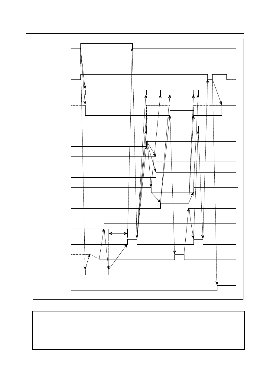
Fig. 10.13.15.2 (d) When gear-change is performed (middle to high gear) 


NOTE 

1  This time chart shows an example where the gear has changed from middle to high 

gear. The PMC selects a required gear through an S code output and selects the 
gear using the GR1 and GR2 signals to inform CNC of the selected gear. 

2  The delay(*) is not necessary, when an appropriate value is set to the parameter 

No.4099 for the delay time for stable motor excitation. 


B-64693EN-1/01


10. SPINDLE SPEED FUNCTION


- 1667 - 

10.13.15.3 

Specifying G84/G74 for rigid tapping by parameters 

  - 

M type gear selection 


M29 

RTAP 

              Motion 1                                               Motion 2 

G84/G74 

M29 is commanded 
internally. 

ENB 

To be masked to the motion 2 

Spindle output 

SF 

GR1O 

GR2O 

GR3O 

*SSTP 

SOR 

250ms 

or more* 

RGTAP 

FIN 

Excitaiton 

SFR 

Position 
loop 

Rotation 


Fig. 10.13.15.3 (a) When gear-change is not performed 


NOTE 


The delay(*) is not necessary, when an appropriate value is set to the parameter 
No.4099 for the delay time for stable motor excitation. 


10. SPINDLE SPEED FUNCTION


B-64693EN-1/01


- 1668 - 


M29 

RTAP 

G84/G74 

ENB 

Spindle output 

SF 

GR1O 

GR2O 

250ms 

or more* 

RGTAP 

FIN 

Rotation 

Gear change 

Excitation 

To be masked to motion 2 

Position 
loop 

                             Motion 1                                Motion 2 

GR3O 

*SSTP 

SOR 


Fig. 10.13.15.3 (b) When gear change is performed (high to low gear) 


NOTE 

1  This time chart shows an example where the gear has shifted from high to low 

gear. One of the gear select signals (GR1O, GR2O, GR3O) has turned from "1" 
to "0", and one of the two remaining signals has turned from "0" to "1". This 
changes the gear. 

2  The delay(*) is not necessary, when an appropriate value is set to the parameter 

No.4099 for the delay time for stable motor excitation. 


B-64693EN-1/01


10. SPINDLE SPEED FUNCTION


- 1669 - 

  - 

T type gear selection method 


M29 

RTAP 

              Motiion 1                                              Motion 2 

G84/G74 

M29 is commanded 
internally. 

ENB 

Spindle output 

SF 

S code output 

GR1 

GR2 

*SSTP 

SOR 

250ms 

or more* 

RGTAP 

FIN 

Rotation   

Excitation 

SFR 

Position 
loop 

To be masked to the motion 2 


Fig. 10.13.15.3 (c) When gear change is not performed 


NOTE 


The delay(*) is not necessary, when an appropriate value is set to the parameter 
No.4099 for the delay time for stable motor excitation. 


10. SPINDLE SPEED FUNCTION


B-64693EN-1/01


- 1670 - 


Position 

loop 

M29 

RTAP 

                             Motion 1                                Motion 2 

G84/G74 

M29 is commanded 
internally. 

ENB 

Spindle output 

SF 

S code output 

GR1 

GR2 

*SSTP 

SOR 

250ms 

or more* 

RGTAP 

FIN 

Rotation 

Gear change 

Excitation 

SFR 

To be masked to the motion 2 


Fig. 10.13.15.3 (d) When gear-change is performed (high to low gear) 


NOTE 

1  This time chart shows an example where the gear has changed from high to low 

gear. The PMC selects a required gear through an S code output and inputs the 
selected gear using the GR1 and GR2 signals to inform CNC of the selected gear.   

2  The delay(*) is not necessary, when an appropriate value is set to the parameter 

No.4099 for the delay time for stable motor excitation. 


B-64693EN-1/01


10. SPINDLE SPEED FUNCTION


- 1671 - 

10.13.15.4 

When M29 is specified before G84/G88 


NC command 


Motion of servo   

axis 

RTAP 


S code output 


SF 


M code output 


MF 


FIN 


*SSTP 


SOR 


GR1/GR2 


SFR/SRV 


RGTAP 


ENB 


Spindle output 


Spindle rotation 


Position loop 

M29 

G84/G88 

Motion 1 

Motion 2 

M29 

C axis clamp 

SFR=1 
SRV=0 

SFR=0 
SRV=0 

Spindle stop 

250ms 
or more* 

To be masked to the 
motion 2 


Fig. 10.13.15.4 (a) When gear change is not performed 


NOTE 


The delay(*) is not necessary, when an appropriate value is set to the parameter 
No.4099 for the delay time for stable motor excitation. 


10. SPINDLE SPEED FUNCTION


B-64693EN-1/01


- 1672 - 


NC command 


Motion of servo 

axis 

RTAP 


S code output 


SF 


M code output 


MF 


FIN 


*SSTP 


SOR 


GR1/GR2 


SFR/SRV 


RGTAP 


ENB 


Spindle output 


Spindle rotation 

Position 

loop 

M29 

Motion 


Motion 2 

G84/G88 

M29 

C axis clamp 

Gear select 

SFR=1 
SRV=0 

SFR=0 
SRV=0 

Spindle stop 

Gear change 

250ms 
or more* 

To be masked to the motion 2 


Fig. 10.13.15.4 (b) When gear change is performed 


NOTE 


The delay(*) is not necessary, when an appropriate value is set to the parameter 
No.4099 for the delay time for stable motor excitation. 


B-64693EN-1/01


10. SPINDLE SPEED FUNCTION


- 1673 - 

10.13.15.5 

M29 and G84/G88 are specified in the same block 


NC command 


Motion of servo 

axis 

RTAP 


S code output 


SF 


M code output 


MF 


FIN 


*SSTP 


SOR 


GR1/GR2 


SFR/SRV 


RGTAP 


ENB 


Spindle output 


Spindle rotation 


Position loop 

G84/G88 M29 

Motion 1 

Motion 2 

M29 

SFR=1 
SRV=0 

SFR=0 
SRV=0 

Spindle stop 

250ms 
or more* 

To be masked to the motion 2 


Fig. 10.13.15.5 (a) When gear-change is not performed 


NOTE 


The delay(*) is not necessary, when an appropriate value is set to the parameter 
No.4099 for the delay time for stable motor excitation. 


Content      ..     212      213      214      215     ..