FANUC Series 0i-MODEL F Plus. CONNECTION MANUAL (FUNCTION) - page 216
 

  Index      Manuals     FANUC Series 0i-MODEL F Plus. CONNECTION MANUAL (FUNCTION) B-64693EN-1/01


Search            copyright infringement  


Content      ..     214      215      216      217     ..


FANUC Series 0i-MODEL F Plus. CONNECTION MANUAL (FUNCTION) - page 216


10. SPINDLE SPEED FUNCTION


B-64693EN-1/01


- 1682 - 

10.13.16.1 

Change the combination for FSSB high-speed rigid tapping 

Outline 

In FSSB high-speed rigid tapping, the combination of spindle axis and servo axis to synchronize can be 
changed after power-on. 
 

Explanation 

This function makes it possible to choose whether to use parameter No.24204 or No.24208 by PMC input 
signals to change the combination of spindle axis and servo axis to synchronize. 
 

Spindle/Servo axes combination change (Parameter change from No.24204 to 

No.24208) 

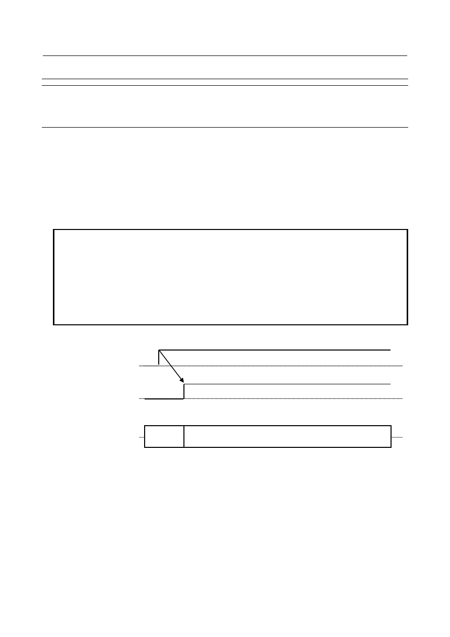
Set Spindle/Servo axis combination change signal SPSVS<G0518.6> from “0” to “1”. After the change 
of spindle/servo axes combination completes, Spindle/Servo axis combination change status signal 
SPSVSS<F0537.1> is set from “0” to “1”. 
 

NOTE 


The alarm (DS0092) “SV/SP COMBINATION ERROR” issues in the following 
cases. 
-  Parameter No.24208 is an illegal setting. 
-  The function using parameter No.24204 (FSSB high-speed rigid tapping, 

Servo/Spindle synchronous control (FSSB type), Electronic gear box (FSSB 
type)) is being applied. 

-  Rigid tapping, Servo/Spindle synchronous control or Electronic gear box is 

being applied in the path that uses parameter No.24208. 

 
Time chart 


Spindle/Servo axes combination change (Parameter change from No.24208 to 

No.24204) 

Set Spindle/Servo axis combination change signal SPSVS<G0518.6> from “1” to “0”. After the change 
of spindle/servo axes combination completes, Spindle/Servo axis combination  change status signal 
SPSVSS<F0537.1> is set from “1” to “0”. 
 

Spindle/Servo axis 
combination change signal 
SPSVS<G0518.6> 

Effective parameter 

Spindle/Servo axis 
combination change 
status signal 
SPSVSS<F0537.1> 

No.24204 

No.24208 

B-64693EN-1/01


10. SPINDLE SPEED FUNCTION


- 1683 - 

NOTE 


The alarm (DS0092) “SV/SP COMBINATION ERROR” issues in the following 
cases. 
-  The function using parameter No.24208 (FSSB high-speed rigid tapping, 

Servo/Spindle synchronous control (FSSB type), Electronic gear box (FSSB 
type)) is being applied. 

-  Rigid tapping, Servo/Spindle synchronous control or Electronic gear box is 

being applied in the path that uses parameter No.24204. 

 
Time chart 


Spindle/Servo axes combination update (Update of parameter No.24208) 

Set Spindle/Servo axis combination update signal SPSVU<G0518.7> from “0” to “1” with Spindle/Servo 
axis combination change status signal SPSVSS<F0537.1> equal to “1”. After the update of spindle/servo 
axes combination completes, Spindle/Servo axis combination update complete signal SPSVUC<F0537.2> 
is set to “1”. 
 

NOTE 


The alarm (DS0092) “SV/SP COMBINATION ERROR” issues in the following 
cases. 
-  Parameter No.24208 is an illegal setting. 
-  The function using parameter No.24208 (FSSB high-speed rigid tapping, 

Servo/Spindle synchronous control (FSSB type), Electronic gear box (FSSB 
type)) is being applied. 

-  Rigid tapping, Servo/Spindle synchronous control or Electronic gear box is 

being applied in the path that uses parameter No.24208. 


Spindle/Servo axis 
combination change signal 
SPSVS<G0518.6> 

Effective parameter 

Spindle/Servo axis 
combination change 
status signal 
SPSVSS<F0537.1> 

No.24208 

No.24204 

10. SPINDLE SPEED FUNCTION


B-64693EN-1/01


- 1684 - 

Time chart 


Signal 

Spindle/Servo axis combination change signal SPSVS<G0518.6> 

  [Classification]  Input signal 
 

[Function]  This signal changes the combination of spindle axis and servo axis to synchronize. 


[Operation]  When setting this signal from “0” to “1”, the parameter to set the combination of spindle 

axis and servo axis to synchronize is changed from No.24204 to No.24208. 


  When setting this signal from “1” to “0”, the parameter to set the combination of spindle 

axis and servo axis to synchronize is changed from No.24208 to No.24204. 


Spindle/Servo axis combination update signal SPSVU<G0518.7> 


[Classification]  Input signal 


[Function]  This signal updates the combination of spindle axis and servo axis to synchronize 

(Parameter No.24208). 


[Operation]  When setting this signal from “0” to “1”, the combination of spindle axis and servo axis 

to synchronize (Parameter No.24208) is updated. This signal is valid when Spindle/Servo 
axis combination change status signal SPSVSS<F0537.1> is equal to “1”.


Spindle/Servo axis combination change status signal SPSVSS<F0537.1> 

  [Classification]  Output signal 
 

[Function]  This signal indicates the status of the change in the combination of spindle axis and servo 

axis to synchronize. 

[Output condition] This signal is set to “1” in the following case: 
 

  - When the parameter to set the combination of spindle axis and servo axis to synchronize 

is changed to No.24208 by Spindle/Servo axis combination change signal 
SPSVS<G0518.6>. 


  This signal is set to “0” in the following case: 

Spindle/Servo axis 
combination update signal 
SPSVU<G0518.7> 

Effective parameter 

Spindle/Servo axis 
combination update 
complete signal 
SPSVUC<F0537.2> 

Parameter No.24208 

before rewrite 

Parameter No.24208 

after rewrite 

Spindle/Servo axis 
combination change signal 
SPSVS<G0518.6> 

Spindle/Servo axis 
combination change 
status signal 
SPSVSS<F0537.1>


Rewrite parameter No.24208 

B-64693EN-1/01


10. SPINDLE SPEED FUNCTION


- 1685 - 


  - When the parameter to set the combination of spindle axis and servo axis to synchronize 

is changed to No.24204 by Spindle/Servo axis combination change signal 
SPSVS<G0518.6>. 


  - When the combination of spindle axis and servo axis to synchronize is not changed by 

Spindle/Servo axis combination change signal. 


Spindle/Servo axis combination update complete signal SPSVUC<F0537.2> 

  [Classification]  Output signal 
 

[Function]  This signal indicates that the combination of spindle axis and servo axis to synchronize 

(Parameter No.24208) has completed being updated. 

[Output condition] This signal is set to “1” in the following case: 
 

  -  When the combination of spindle axis and servo axis to synchronize (Parameter 

No.24208) is updated by Spindle/Servo axis combination update signal 
SPSVU<G0518.7>. 


  This signal is set to “0” in the following case: 


  - When Spindle/Servo axis combination update signal SPSVU<G0518.7> is set to “0”. 


Signal address 


#7 

#6 

#5 

#4 

#3 

#2 

#1 

#0 

G0518 


SPSVU 

SPSVS 


#7 

#6 

#5 

#4 

#3 

#2 

#1 

#0 

F0537 


SPSVUC 

SPSVSS 


Notes 

When the alarm (DS0092) "SV/SP COMBINATION ERROR" is issued, the combination of spindle 
axis and servo axis is not updated and remains in the last status. 

When controlling Spindle/Servo axis combination change signal SPSVS<G0518.6> or 
Spindle/Servo axis combination update signal SPSVU<G0518.7> during operation, use M codes that 
do not perform Buffering. 

Parameter No.24204 can be replaced with parameter No.24208 by this function when applying the 
functions that use parameter No.24204, other than FSSB high-speed rigid tapping. 

When applying this  function, check the ready status with All-spindle operation ready signal 
SRSRDY<F0034.7> after power-on. 


10. SPINDLE SPEED FUNCTION


B-64693EN-1/01


- 1686 - 

10.13.17 

Smart Rigid Tapping 

Outline 

Smart rigid tapping is the tapping function that uses maximum spindle power in all speed range. As the 
servo axis follows spindle axis with using FSSB communication, the synchronous error is small. 
The fastest rigid tapping can be achieved with no parameter tuning basically. 


Fig. 10.13.17 (a)    Smart rigid tapping 

 
Application example of smart rigid tapping (Pitch 1mm, Length25mm) 
 

Before applying Smart rigid tapping 


After applying Smart rigid tapping 


Fig. 10.13.17 (b)    Application example of smart rigid tapping 


Spindle speed 

At extraction : 
Same movement as cutting 

Full torque acceleration 
in velocity control 

Velocity control 

Deceleration by tolerable acc. in position control 

Detecting 
torelable acceleraion 

Bottom of tap 

Time 

Pos. ctrl. 

Pos. ctrl. 

Velocity control 

Spindle speed 
(2000min

-1

/div) 

Servo speed 
(200min

-1

/div) 

Spindle torque 
command (100%/div) 

Synchronous error (50pulse/div) 

Acc/Dec by spindle maximum power 

Keeping the small synchronous error 
even in short cycle time 

25% reduced (ex.) 

B-64693EN-1/01


10. SPINDLE SPEED FUNCTION


- 1687 - 

Program Format 

The program format for Smart rigid tapping is same as ordinal rigid tapping. But if the moving distance of 
tapping is larger than over 4096 times of screw pitch, the alarm PS0564, "ILLEGAL COMMAND OF 
SMART RTAP" will occur. 
 

DI/DO Signals and Sequence 

The DI/DO signals and PMC sequence for ordinal rigid tapping can be used without any change. There is 
no special DI/DO signals and PMC sequence for Smart rigid tapping. 
Regarding DI/DO signals and PMC sequence, refer to the chapter of "Signal" and "Timing Charts for 
Rigid Tapping Specification" in this manual. 
 

Parameters 

Settings for FSSB high-speed rigid tapping 
 

Set all parameters related to FSSB high-speed  rigid tapping so that the servo axis follows spindle 
axis. The detail of setting parameters are shown in the chapter of "FSSB high-speed rigid tapping" 
and "Parameter" in this manual. 


Table 10.13.17 (a)  Settings for FSSB high-speed rigid tapping 

Parameter No. 

Contents 

Setting value 

2005#1 

Feed-forward function bit (Servo) 

2429#1 

FSSB high-speed rigid tapping function bit (Servo) 

2610 

Position gain of servo axis during FSSB high-speed rigid tapping 

5000 

4549#1 

FSSB high-speed rigid tapping function bit (Spindle) 

24203#0 

FSSB high-speed rigid tapping function bit (CNC) 

24204 

The index number of the spindle axis that synchronizes to each 
servo axis 

Depends on 

configuration 

 
Settings for Smart rigid tapping 
 

After setting of following parameters the settings for Smart rigid tapping will be finished in case that 
the settings for Normal rigid tapping has been already done. In case that the settings for Normal rigid 
tapping has not been done yet, do it with referring to chapter of "Parameter" in this manual, or the 
chapter of "Rigid tapping" in FANUC AC SPINDLE MOTOR 

a

i

/

β

i

  series BUILT-IN SPINDLE 

MOTOR B

i

 series parameter manual (B-65280EN). 


Table 10.13.17 (b)    Settings for Smart rigid tapping 

Parameter No. 

Contents 

Setting value 

5206#1 

Smart rigid tapping function bit 

2423#2 

Setting for the compensation of reverse operation in Smart rigid 
tapping 

5214 

Setting of an allowable rigid tapping synchronous error range 

4105 
4107 

Time constant of magnetic flux for Magnetic flux control 

Specific 

parameter 

for each motor 

4661 

Tolerable error value at spindle stop 


Settings for Each Machine 

As Smart rigid tapping accelerates by maximum spindle power, the tuning is not necessary basically. But 
there may be some cases that a shock occurs in servo axis which follows spindle acc./dec. by maximum 
power. In such case, use following parameters. 
 
Parameters for tuning Smart rigid tapping 
 

10. SPINDLE SPEED FUNCTION


B-64693EN-1/01


- 1688 - 

Table 10.13.17 (c)    Parameters for tuning Smart rigid tapping 

Parameter No. 

Contents 

Setting value 

4666 
4667 

Bell shape acc./dec. time constant for Smart rigid tapping 

4668 
4669 

Upper limit of torque command for Smart rigid tapping 

4395#5 

Improvement of deceleration for Smart rigid tapping 

4790 

Lower limit of torque command for Smart rigid tapping in position 
control 

2611 

Coefficient of velocity feed-forward for feed axis in Smart rigid 
tapping 

2613 

Compensation of reverse operation in Smart rigid tapping 

 
Settings for Smart thermal control 
 

As Smart rigid tapping uses maximum spindle power in tapping, there is a possibility that the motor 
overheat alarm (SP9001) might occur in severe duty tapping. 


Smart thermal control uses the spindle motor power at the best without motor overheat. 


Regarding the detail of Smart thermal control, refer to FANUC AC SPINDLE MOTOR 

a

i

/

β

i

 series 

BUILT-IN SPINDLE MOTOR B

i

 series parameter manual (B-65280EN). 

 
Settings for rigid tapping during dry run 
 

Rigid tapping during dry run can be selected by bit 2 (NSD) of parameter No.5206 from Smart rigid 
tapping or ordinal FSSB high-speed rigid tapping. Set 1 to bit 2 (NSD) of parameter No.5206 which 
is described below if you make override effective during dry run. 


Bit 2 (NSD) of parameter No.5206 is 0 
 

Rigid tapping during dry run is Smart rigid tapping. 


-


Feedrate cannot be changed by manual feedrate override signal *JV0 to *JV15<Gn010, 

Gn011> or manual rapid traverse selection signal RT<Gn019.7>. 

-


If dry run is canceled during Smart rigid tapping in dry run, feedrate is maintained until 

finishing tapping. 

-


If dry run is switched during Smart rigid tapping, feedrate is maintained until finishing 

tapping. 


Bit 2 (NSD) of parameter No.5206 is 1 
 

Rigid tapping during dry run is ordinal FSSB high-speed rigid tapping. 


-


Feedrate can be changed by manual feedrate override signal *JV0 to *JV15<Gn010, 

Gn011> or manual rapid traverse selection signal RT<Gn019.7>. 

-


If dry run is canceled during FSSB high-speed rigid tapping in dry run, feedrate is 

changed from dry run feedrate to feedrate commanded in machining program. 

-


If dry run is switched during Smart rigid tapping, Smart rigid tapping is continued and 

feedrate is maintained until finishing tapping. 

-


Acc./dec. time constant setting is necessary because ordinal FSSB high-speed rigid 

tapping is executed during dry run. Adjustment of optimal time constant is unnecessary. Set 
relative long time constant such as 500[msec] to parameter No.5261 to No.5264. Refer to 
"Parameter list related to Normal rigid tapping" for detail. 


B-64693EN-1/01


10. SPINDLE SPEED FUNCTION


- 1689 - 

Tuning of Rigid Tapping 

Common used parameter list 
 

The following parameter list show the common used parameters both for Normal rigid tapping and 
Smart rigid tapping. In case that the tuning for Normal rigid tapping has finished, it’s not necessary 
to change these parameters. Regarding the detail of each parameter, refer to the chapter of 
"Parameter" in this manual or the chapter of "Rigid tapping" in FANUC AC  SPINDLE MOTOR 

a

i

/

β

i

 series BUILT-IN SPINDLE MOTOR B

i

 series parameter manual (B-65280EN). 


Table 10.13.17 (d)    Common used parameter list 

Parameter No. 

Contents 

5210 

Rigid tapping mode specification M code 

5202#0 

Whether to perform orientation (reference position return) when starting rigid tapping 

5221 
5222 
5223 
5224 

Teeth number of spindle side at arbitrary gear ratio (command) setting 
(No. 5224 is used for the T series only.) 

5231 
5232 
5233 
5234 

Teeth number of position coder side at arbitrary gear ratio (command) setting 
(No. 5234 is used for the T series only.) 

5241 
5242 
5243 
5244 

Spindle maximum speed at rigid tapping 
(No.5244 is used for the T series only.) 

5200#4 

Override selection at extracting 

5211 

Override value at extracting 

5300 
5302 
5304 
5306 

In-position width of tapping axis 

5301 

In-position width of spindle 

4000#4 

Reference position return direction on servo mode 

4002#5 

Whether to enable the rotation direction signal (SFR/SRV) on servo mode 

4006#7 

Setting of the command arbitrary gear ratio function (CMR) on rigid tapping 

4017#7 

Shortcut function when orientation is specified in stop state 

4044 
4045 

Velocity loop proportional gain on servo mode 
(It is selected by input signal CTH1A/B.) 

4052 
4053 

Velocity loop integral gain on servo mode 
(It is selected by input signal CTH1A/B.) 

4056 to 4059 

Gear ratio between spindle and motor 
(It is selected by input signal CTH1A or CTH2A) 

4065 to 4068 

Spindle position gain on servo mode/spindle synchronous control 
(It is selected by input signal CTH1A or CTH2A) 

4073 

Grid shift amount on servo mode 

4074 

Reference position return speed on servo mode 

4091 

Position gain change ratio at reference position return time on servo mode 

4099 

Delay time for stable motor excitation 

4171 
4173 

Denominator of an arbitrary gear ratio between the motor sensor and spindle 
(It is selected by input signal CTH1A or CTH2A.) 

4172 
4174 

Numerator of an arbitrary gear ratio between the motor sensor and spindle 
(It is selected by input signal CTH1A or CTH2A.) 

4406 

Acceleration/deceleration time constant for Cs contouring control/servo mode 


Content      ..     214      215      216      217     ..