FANUC Series 0i-MODEL F Plus. CONNECTION MANUAL (FUNCTION) - page 173
8. MULTI-PATH CONTROL
B-64693EN-1/01
- 1338 -
1. In case of bit 2 (NCA) of parameter No.11284 is set to 0 (Conventional specification)
The forbidden area is composed from the axes actually controlled according to the exchanging of Z
axes on Composite control, as shown in Fig. 8.6.2 (e).
Composite control of
Z1 and Z2 axes
Z1
X1
Z2
X2
Forbidden area
is composed from
Z1 and X1 axes
X2
Z2
Z1
X1
Forbidden area
is composed from
Z2 and X2 axes
Forbidden area
is composed from
Z2 and X1 axes
Forbidden area
is composed from
Z1 and X2 axes
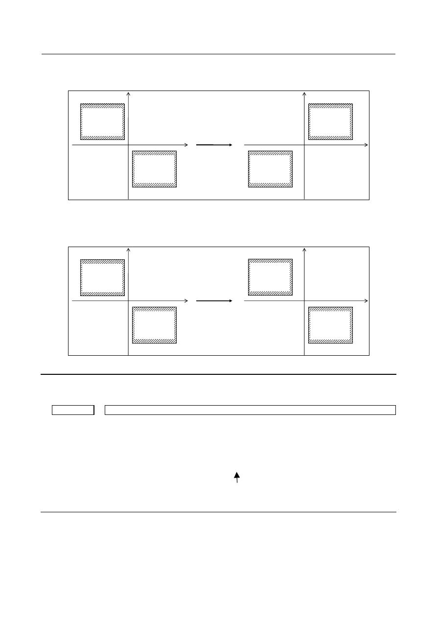
Fig. 8.6.2 (e) Composite control and the inside forbidden area (Existing specification)
2. In case of bit 2 (NCA) of parameter No.11284 is set to 1 (Compatible specification with
FS0
i
-TTC)
The forbidden area is kept even if Composite control is executed, as shown in Fig. 8.6.2 (f).
Composite control of
Z1 and Z2 axes
Z1
X1
Z2
X2
Forbidden area
is composed from
Z1 and X1 axes
X1
Z2
Z1
X2
Forbidden area
is composed from
Z2 and X2 axes
Forbidden area
is composed from
Z2 and X2 axes
Forbidden area
is composed from
Z1 and X1 axes
Fig. 8.6.2 (f) Composite control and the inside forbidden area (Compatible specification with FS0
i
-TTC’s)
Diagnosis data
The diagnosis data displays synchronous errors.
3502
Display of synchronous error for each axis
[Unit of data] Detection unit
[Meaning] Displays the difference between the master and slave axes in position deviation if
synchronous deviation detection is performed (bit 1 (SERx) of parameter No. 8162 =1).
The positional deviation difference is:
(positional deviation of the master axis)
±
(positional deviation of the slave axis)
+ if a mirror image is applied to the synchronization command.
- if no mirror image is applied to the synchronization command.
Alarm and message
If any of the following alarms occurs, synchronous or composite control will be canceled for all axes.