FANUC Series 0i-MODEL F Plus. CONNECTION MANUAL (FUNCTION) - page 170
 

  Index      Manuals     FANUC Series 0i-MODEL F Plus. CONNECTION MANUAL (FUNCTION) B-64693EN-1/01


Search            copyright infringement  


Content      ..     168      169      170      171     ..


FANUC Series 0i-MODEL F Plus. CONNECTION MANUAL (FUNCTION) - page 170


8. MULTI-PATH CONTROL


B-64693EN-1/01


- 1314 - 

8.6 

SYNCHRONOUS/COMPOSITE CONTROL 

Overview 

Multi-path control, which has multiple independent control paths built in, is used for such purposes as 
controlling multiple turrets of a complex lathe. The axes (such as X1-and Z1-axes) belonging to path 1 
are controlled by commands in path 1, and the axes (such as X2- and Z2-axes) belonging to path 2 are 
controlled by commands in path 2. 
 

  - 

Independent control in each path 


Turret 1 

Turret 2 

Workpiece 2 

Workpiece 1 


X2 

X1 

Z1 

Z2 

Machining is performed 
by a path 1 program. 

Machining is performed 
by a path 2 program. 


Fig. 8.6 (a) 

 
This function enables synchronous control between paths or within a path, composite control between 
paths, and superimposed control between paths, as explained below. 
 

  - 

Synchronous control 

Synchronization of an axis in one path with an axis in another path 
(Example) 
 

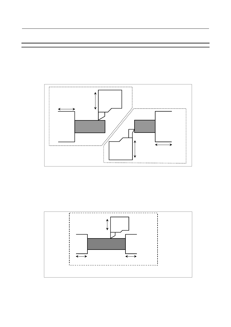
Synchronization of the Z1-axis (master) with the Z2-axis (slave) 


Workpiece 

Z2 (synchronized with 
the Z1-axis) 

Z1 

Turret 1 

X1 

Machining is performed by a path 1 program. 


Fig. 8.6 (b) 


B-64693EN-1/01


8. MULTI-PATH CONTROL


- 1315 - 

Synchronization of an axis in one path with another axis in the same path 
(Example) 
 

Synchronization of the Z1-axis (master) with the B1-axis (slave) 


Workpiece   

B1 (synchronized with the Z1-axis) 

Z1 

Turret 1 

X1 

Tail stock 


Fig. 8.6 (c) 


  - 

Composite control 

Interchanging move commands for an axis in one path with those for an axis in another path. 
(Example) 
 

Interchanging commands between the X1- and X2-axes 

  Control both X2- and Z1-axes by commands in a path 1 program 


Control both X1- and Z2-axes by commands in a path 2 program 


Turret 1 

Turret 2 

Workpiece 2 

Workpiece 1 

X2 

X1 

Z1 

Z2 

Machining is performed 
by a path 1 program. 

Machining is performed 
by a path 2 program. 


Fig. 8.6 (d) 


8.6.1 

Synchronous Control 

An axis in one path can be synchronized with another axis in the same path or an axis in another path. 
This is done by issuing the same move commands for one axis (synchronous master axis) to another axis 
(synchronous slave axis). Using bit 0 (SMRx) of parameter No. 8162 can cause the slave axis to move in 
the direction opposite to that of the master axis. It is possible to place either the master or slave axis in a 
parking state, which means to discontinue giving move commands to a servo system. No coordinates are 
updated in the parking state. However, the absolute and relative coordinates can be updated using bit 2 
(PKUx) of parameter No. 8162. 
 

8. MULTI-PATH CONTROL


B-64693EN-1/01


- 1316 - 

Explanation 

  - 

Setting 

Specify which axis is to be the synchronous master axis, with parameter No. 8180, using the path number 
and the axis number. 
(Example) 
 

For an axis configuration in which all paths consist of X, Z, and Y axes 


To synchronize the Z4-axis (slave) with the Z1-axis (master): 


Parameter No. 8180z of path 4 = 102 


To synchronize the X8-axis (slave) with the X5-axis (master): 


Parameter No. 8180x of path 8 = 501 


To synchronize the Y1-axis (slave) with the X1-axis (master): 


Parameter No. 8180y of path 1 = 101 


  - 

Programming 

Both before and after the M codes for a start and a cancellation of synchronous control, specify a waiting 
M code. 
Master axis path 

Slave axis path 

  : 

  : 

M100P12; 

M100P12; .................... Waiting 


M200; ........................... Start of synchronous control 

M101P12; 

M101P12; .................... Waiting 

  : 

  : 

Independent operation  Independent operation 
  : 

  : 

M100P12; 

M100P12; .................... Waiting 


M201;   ......................... Cancellation of synchronous control 

M101P12; 

M101P12; .................... Waiting 

  : 

  : 


  - 

Signal operation 

When synchronization begins or ends (when an M code is issued, for example), the synchronous control 
axis selection signals SYNC1 to SYNC8<Gn138> for the slave axis (from the PMC to the CNC) are 
changed from "0" to "1" (to begin synchronization) or from "1" to "0" (to terminate synchronization). To 
place an axis in a parking state, a parking signal PK1 to PK8<Gn122> is set to "1" for the target axis. 
 

  - 

Examples of applications 

The following operations can be performed by using the synchronization functions together with the 
parking function, which causes move commands for an axis to be ignored and keeps the axis at a rest. 
(1)  Moving an axis in one path in synchronization with an axis in another path (Both master and slave 

axes move.) 
Example 1) 
 

Synchronizing the Z2-axis (slave) with the Z1-axis (master) (machining with both ends of a 
workpiece chucked) 


Z2 (synchronized with the Z1-axis) 

Z1 

Turret 1 

X1 


Fig. 8.6.1 (a) 

B-64693EN-1/01


8. MULTI-PATH CONTROL


- 1317 - 

Example 2) 
 

Synchronizing the X2- and Z2-axes (master) with the X1- and Z1-axes (slave) (balance cutting) 


Turret 1 

X1 

Turret 2 

X2 

Z2 

Z1 


Fig. 8.6.1 (b) 


Example 3) 
 

Synchronizing the B1-axis (slave) (tail stock axis) with the Z1-axis (master) 


Workpiece 1 

B1 (synchronized with the Z1-axis) 

Z1 

Turret 1 

X1 

Tail stock 


Fig. 8.6.1 (c) 

 
(2)  Placing the movement along the synchronous master axis in the stopped state using a parking signal 

is referred to as master parking. In this state, the tool will move along the slave axes only. In contrast, 
placing the synchronous slave axes in the stopped state is referred to as slave parking. In this state, 
the tool will move along the master axis only. This makes it possible to control a single motor from 
both paths 1 and 2. 


Example 4) 
 

Sharing one motor with the Z1- and Z2-axes (assuming that the motor is linked to the Z1-axis) 


  Master axis parking 


Turret 1 

X1 

Z1 

Turret 2 

X2 

The X2- and Z1-axes are moved by commands 
in a path 2 program (by synchronizing the 
Z1-axis (slave) with the Z2-axis (master)). At this 
point, the Z2-axis (master) is kept in a parking 
state. 


Fig. 8.6.1 (d) 

8. MULTI-PATH CONTROL


B-64693EN-1/01


- 1318 - 


  Slave axis parking 


Turret 1 

X1 

Z1 

Turret 2 

X2 

The X1- and Z1-axes are moved by commands in 
a path 1 program (by synchronizing the Z2-axis 
(slave) with the Z1-axis (master)). At this point, 
the Z2-axis (slave) is kept in a parking state. 


Fig. 8.6.1 (e) 

 
Parking causes the positional relations between machine, absolute, and relative coordinates to shift. After 
reference position return, therefore, set the workpiece coordinate system. 


  - 

Reference position return and its check during synchronous control 

If a reference position return command is issued for a synchronous master axis during synchronous 
control, it is executed normally for the master axis, but the slave axis does not return to its reference 
position (the slave axis only moves in synchronization with the reference position return of the master 
axis).   
An exception is for automatic reference position return (G28) issued when the master axis is in a parking 
state, in which the amount of movement is calculated so that the slave axis returns to its reference position. 
In this case, a reference position return has been carried for the slave axis. If the reference position of the 
slave axis has not been established, alarm PS0354 “THE G28 WAS INSTRUCTED IN WITH THE REF 
POS NOT FIXED IN SYNC MODE” will result. 

 
If, in Cs axis synchronous control, the master axis is not in the parking state and the reference position of 
the master  axis has not been established, a reference position return operation will be performed in 
reference to the master axis machine position, with the G28 command for the master axis. 
If the master axis is in the parking state and the reference position of the  slave axis has not been 
established, a reference position return operation will be performed in reference to the slave axis machine 
position, with the G28 command for the master axis. 

 
If more than one slave axis belongs to one master axis, a reference position return command is executed 
so that the lowest-numbered slave axis returns to its reference position. If the master axis in one path is 
subjected to both synchronization with an axis in the same path and synchronization with an axis in the 
other path  simultaneously, the lowest-numbered slave axis in the two paths is moved to the reference 
position. 
 
A return to the second (third or fourth) reference position by the G30 command works in the same way as 
G28. In other words, usually only the master axis moves to the second (third or fourth) reference position. 
If the master axis is parking, the lowest-numbered axis is caused to move to its second (third or fourth) 
reference position. 
If a reference position return check (G27) is specified during synchronous control, the master and slave 
axes move to the specified position. Upon completion of movement, a check is made to see whether the 
master axis is at its reference position (no check is made for the salve axes) unless the master axis is in a 
parking state, in which case a check is made upon completion of positioning to see whether the 
lowest-numbered slave axis is at its reference position. 
 

B-64693EN-1/01


8. MULTI-PATH CONTROL


- 1319 - 

  - 

Out-of-synchronization detection 

The term synchronous control used here only refers to an operation in which the same move command is 
issued to multiple different servo systems at one time. Note that synchronous control does not involve 
out-of-synchronization compensation, in which the positional deviation between multiple servo motors is 
constantly checked and one of the servo motors is subjected to compensation to reduce the deviation. 
However, using bit 1 (SERx) of parameter No. 8162 can specify detection of out-of-synchronization. 
When the out-of-synchronization state is detected, the synchronization mode is canceled immediately 
using bit 6 (SESx) of parameter No. 8169, alarm SV0407, “EXCESS ERROR” is issued and the servo 
ready signal is turned off, or the excess synchronization error signal SEO <Fn559> is output. 
 

  - 

Automatic setting of a workpiece coordinate system 

When synchronous control is started in a workpiece coordinate system, it is possible to specify the 
workpiece coordinate system automatically. When synchronous control for a workpiece coordinate 
system is terminated, it is possible to return the workpiece coordinate system to ordinary machining (not 
synchronous control). The explanation of the workpiece coordinate system used during synchronous 
control follows. When synchronous control is used to move an axis differently from the way originally 
specified, for example, the master axis may be placed in a parking state, while the slave axis is allowed to 
move. In such a case, it will be convenient if a coordinate system that indicates the current position of the 
slave axis is used as a workpiece coordinate system for the master axis. Conventionally, this workpiece 
coordinate system must be specified by program when synchronous control is started, because the 
workpiece coordinate system does not originally belong to the master axis. This automatic workpiece 
coordinate system setting function for synchronous control sets up this workpiece coordinate system 
automatically. This function can also resume the original workpiece coordinate system for the master axis 
automatically. Note that the workpiece coordinates  of a salve axis can be automatically set through 
appropriate parameter setting at the end of synchronous control only. 
 

  - 

Setting and commands 

In addition to setting ordinary synchronous control, parameters must be specified as follows: 
(1)  To set up a workpiece coordinate system for synchronous control automatically when starting 

synchronous control 
Set bit 1 (SPMx) of parameter No. 8163 to 1. 


Set parameter No. 8185 with the coordinates of the slave axis reference position relative to the 
coordinates of the master axis when the master axis is at the reference position. 

(2)  To resume the ordinary workpiece coordinate system automatically when terminating synchronous 

control 
Set bit 2 (SPSx) of parameter No. 8163 to 1. (Only the parameter of the master axis.) 
Set parameter No. 1250 with the master axis coordinates in the workpiece coordinate system when 
the master axis is at the reference position. 


This synchronous control can be specified using the synchronous control axis selection signals 
(SYNC1 to SYNC8) similarly to the ordinary synchronous control. When the signals are raised to 
start synchronous control, a workpiece coordinate system for the master axis is automatically set up. 
When the signals are dropped to terminate synchronous control, the original workpiece coordinate 
system for the master axis is resumed automatically. 


  - 

Workpiece coordinate calculation method 

(1)  Workpiece coordinate system for synchronous control 

(Master axis workpiece coordinate value) = (parameter No. 8185 for the master axis) 
 

±

 (slave axis machine coordinate value) .............. <1> 


+ (master axis machine coordinate value) ............ <2> 

<1>  +: Bit 4 (SCDx) of parameter No. 8163 for the master axis = 0 

-: Bit 4 (SCDx) of parameter No. 8163 for the master axis = 1 

<2>  Bit 3 (SCMx) of parameter No. 8163 for the master axis = 1 only 


8. MULTI-PATH CONTROL


B-64693EN-1/01


- 1320 - 

(2)  Workpiece coordinate system for ordinary operation 

(Master axis workpiece coordinate value) 
  = (parameter No. 1250 for the master axis) +(master axis machine coordinate value) 


Caution 

  CAUTION 


The same least command and input increments must apply to both master and 
slave axes. 


Note 

NOTE 

1  If more than one slave axis is synchronized with one master axis, the master 

axis is set with the workpiece coordinate system that corresponds to the current 
position of the first slave axis that is synchronized with the master axis. 

2  A coordinate system can also be set with consideration given to tool offset, 

through appropriate parameter settings. So, the coordinate system is set up 
normally even when tool geometry compensation is applied. 


8.6.2 

Composite Control 

Move commands can be interchanged between an axis in one path and an axis in another path. In other 
words, when a machining program is executed for one path, actual machining can be performed with an 
axis in the other path. Coordinate systems can also be switched automatically between independent 
control and composite control. 
 

Explanation 

  - 

Setting 

Specify which axis is to interchange with which axis, with parameter No. 8183, using the path numbers 
and the axis numbers. 
Example) 
 

For an axis configuration in which all paths consist of X, Z, and Y axes 


Between the Z1- and Z4-axes:   


Parameter No. 8183z of path 4 = 102 

Between the X5- and X8-axes: 


Parameter No. 8183x of path 8 = 501 

Between the X1- and Y2-axes: 


Parameter No. 8183y of path 2 = 101 

 
To set up coordinate systems automatically when composite control begins or ends, set bits 4 (MPMx) 
and 5 (MPSx) of parameter No. 8162 to 1, and specify the positional relationship between the coordinate 
systems in parameter No. 8184. 
 

  - 

Programming 

Both before and after the M codes for a start and a cancellation of composite control, specify a waiting M 
code. 
Composite control source  Composite control destination 
  : 

  : 

M100P12; 

M100P12; ............................... Waiting 


M210;...................................... Start of composite control 

M101P12; 

M101P12; ............................... Waiting 

  : 

  : 

Independent operation 

Independent operation 

  : 

  : 

B-64693EN-1/01


8. MULTI-PATH CONTROL


- 1321 - 

M100P12; 

M100P12; ............................... Waiting 


M211;  .................................... Cancellation of composite control 

M101P12; 

M101P12; ............................... Waiting 

  : 

  : 


  - 

Signal operation 

When you want to start or cancel composite control (when you specify an M code, for example), change 
the composite control axis select signal between MIX1 and MIX8<Gn128> for the axis subject to 
composite control that is specified with parameter No. 8183 (the signal being sent from the PMC to the 
CNC) from "0" to "1" (to start composite control) and from "1" to "0" (to cancel composite control). 
 

  - 

Examples of applications 

Suppose that a machine has the X1- and Z1-axes belonging to path 1 and the X2- and Z2-axes belonging 
to path 2 and that a workpiece moves along the Z1-  and Z2-axes as directed by move commands. The 
following examples interchange commands between the X1- and X2-axes. 
 
(1)  Independent control 


Turret 1 

Turret 2 

Workpiece 2 

Workpiece 1 

X2 

X1 

Z1 

Z2 

Machining is performed by a path 1 program. 

Machining is performed by a path 2 program. 


Fig. 8.6.2 (a) 

 
(2)  Composite control 


Turret 1 

Turret 2 

Workpiece 2 

Workpiece 1 

X2 

X1 

Z1 

Z2 

Machining is performed by a path 1 program. 

Machining is performed by a path 2 program. 


Fig. 8.6.2 (b) 


Content      ..     168      169      170      171     ..