FANUC Series 0i-MODEL F Plus. CONNECTION MANUAL (FUNCTION) - page 168
 

  Index      Manuals     FANUC Series 0i-MODEL F Plus. CONNECTION MANUAL (FUNCTION) B-64693EN-1/01


Search            copyright infringement  


Content      ..     166      167      168      169     ..


FANUC Series 0i-MODEL F Plus. CONNECTION MANUAL (FUNCTION) - page 168


8. MULTI-PATH CONTROL


B-64693EN-1/01


- 1298 - 

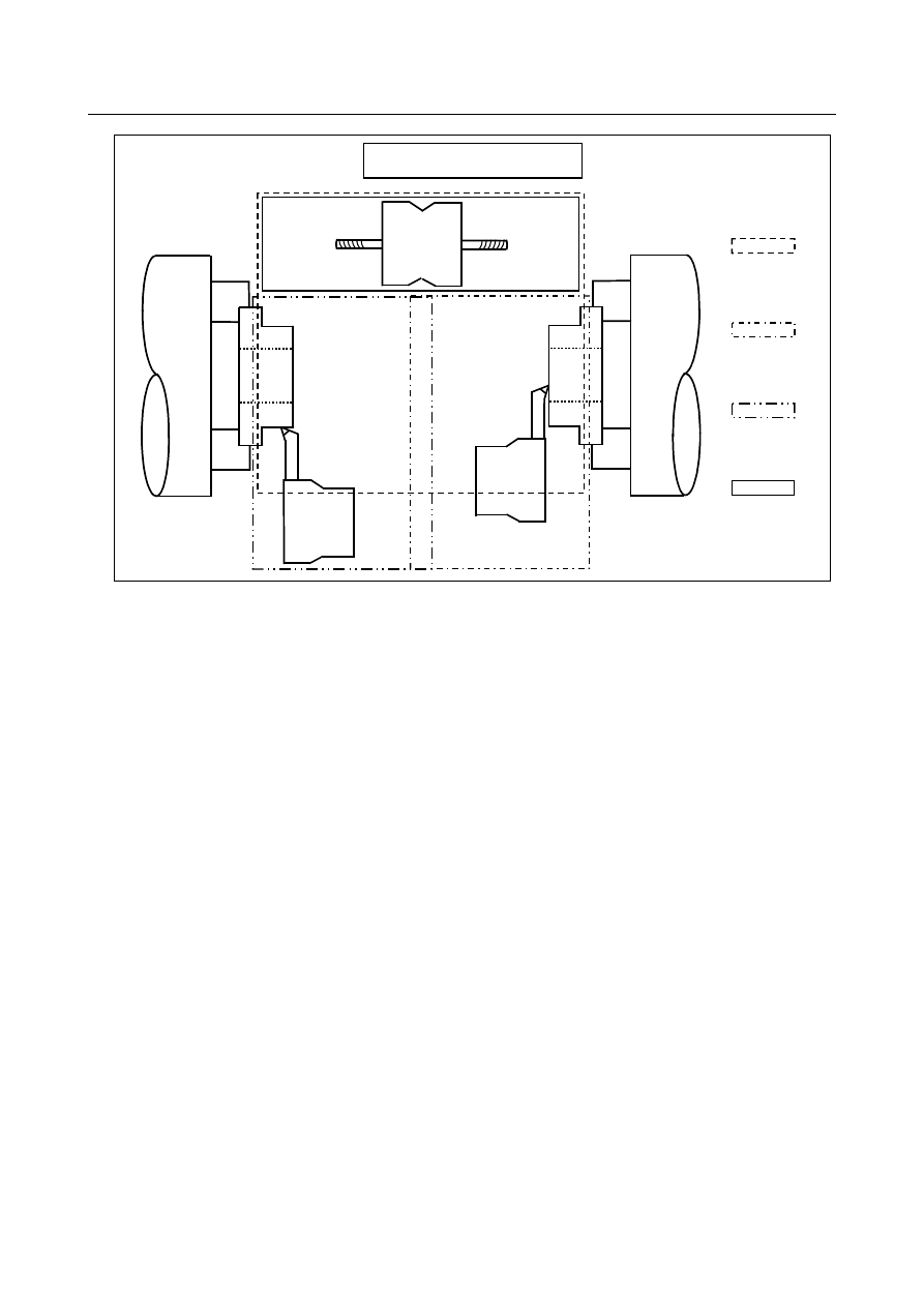
Tool post 3

Tool post 2

Three-path machine configuration

Tool post 1

Operation range
of tool post 1

Operation range
of tool post 2

Operation range
of tool post 3

Safety pocket for
tool post 1


Fig. 8.4 (g) 

 
For example, Fig. 8.4 (g), when the operation range of tool post 1 on path 1 overlaps with that of tool post 
2 on path 2 and that of tool post 3 on path 3 as shown above, an interference check is required. In this 
sample machine configuration, however, tool post 1 is always positioned within the safety pocket in 
which the tool post does not interfere with path 2 or 3 when tool post 2 or 3 operates. In this case, for 
signals Gn406 for path 1, set the signals corresponding to paths 2 and 3 to 1 because an interference 
check must be made for the paths. 

Path 1 

Gn406 = 00000111 

 
Paths 2 and 3 do not interfere with path 1, but the operation ranges of tool posts 2 and 3 overlap each 
other. In this case, an interference check is required and the setting is as follows: 

Path 2 

Gn406 = 00000110 

Path 3 

Gn406 = 00000110 


B-64693EN-1/01


8. MULTI-PATH CONTROL


- 1299 - 

  - 

Setting the interference forbidden area (setting common to conventional and 
multipath specifications) 

An interference forbidden area is set using a combination of two rectangular areas. The examples are 
shown below. 


(Example 1) 

Area 1

Area 2

Area 2

Area 1

or


Fig. 8.4 (h) 


(Example 2) 

Area 2

Area 1


Fig. 8.4 (i) 

 
The relative coordinates of the upper and lower ends (points A and B and points C and D shown below) 
of each of two rectangles are set, with the reference position of the tool post set as the origin. 

Area 1

Area 2

A (X

1

, Z

1

)

B (I

1

, K

1

)

C (X

2

, Z

2

)

D (I

2

, K

2

)

Reference
position

+Z

+X

X

1

 > I

1

Z

1

 > K

1

X

2

 > I

2

Z

2

 > K

2


Fig. 8.4 (j) 


Display and setting of an interference forbidden area in a multipath 
interference check 

Display and set tool figure data (interference forbidden area) by performing the following operations: 
(1)  With the path selection signal, select a path for which an interference forbidden area is to be 

displayed and set in a multipath interference check. 

(2)  Press the function key 


(3)  Press the chapter selection soft key [TOOL FIGURE]. 

8. MULTI-PATH CONTROL


B-64693EN-1/01


- 1300 - 

(4)  Display the screen including a tool number for which data is to be set. 

Method 1: 

Switch the screen display by pressing the page key or cursor key. 

Method 2: 

Enter a tool number to be set then press the [NO.SRH] soft key. 


Fig. 8.4 (k) 

 
(5)  With the cursor keys, move the cursor to data to be set. 

(When setting data for point A, move the cursor to X and Z. When setting data for point B, move the 
cursor to I and K.) 

(6)  Enter the coordinate values of point A or point B by using numeric keys. 

(The decimal point can also be entered.) 
Enter the coordinate values of point A or point B by using numeric keys. 
(The decimal point can also be entered.) 


A (X, Z) 

B (I, K) 

Reference position 

+Z 

+X 

X > I 

Z > K 


Fig. 8.4 (l) 

 
(7)  By pressing the soft key [INPUT], the entered coordinate values are set. 

(To add an entered value to the already set data, press the soft key [+INPUT].) 
 

NOTE 

Tool number 
 

Tool figure data needs to be set for each tool number. A tool number used 
here means an offset number. When both of geometry offset and wear offset 
are used, a tool number corresponds to a wear offset number. When multiple 
offset numbers are used for the same tool, the same data needs to be set as 
tool figure data. 


  - 

Conditions for Making a Path Interference Check 

A path interference check is made when conditions listed below are satisfied. 

B-64693EN-1/01


8. MULTI-PATH CONTROL


- 1301 - 

  (1)  Common conditions 

Bit 4 (IFE) of parameter No. 8140 for enabling the path interference check function is set to 0. 

The X-  and Z-axes of the three basic axes are set for parameter No. 1022 for individual paths for 
which a path interference check is to be made. 

After power is turned on, reference point return operation is completed with all axes. (When an 
absolute-position detector is used, the matching between a machine position and absolute-position 
detector position must be completed.) 

Offset numbers other than 0 are specified using T codes for tool posts on the paths for which a path 
interference check is made. 

Values are input in either one or both of the areas of the tool shape data corresponding to the 
specified tool number and the relationships among the values are X > I and Z > K. 

When manual mode is used, bit 3 (IFM) of parameter No. 8140 for enabling the interference check 
for each path function in manual mode is set to 1. 


  (2)  Conditions for a multipath interference check 

A multipath interference check is made when the conditions below as well as the common conditions are 
satisfied: 

Bit 7 (IFP) of parameter No. 8140 for enabling the multipath interference check function is set to 1. 

The path associated with each signal of Gn406 for each path exists. 


  (3)  When the interference check conditions are satisfied 

When all conditions for making a path interference check are satisfied, the 
path-interference-check-in-progress signal is output to the PMC. 
 

  WARNING 


To make a path interference check, the tool number for which tool shape data is 
input must agree with the programmed tool number. An interference check 
cannot be made correctly if the tool is selected by manual operation or if no tool 
select command is specified at power-on. 


Signal 

  - 

For a check for interference between two paths 

Path interference check in progress signal TICHK<F0064.6> 

  [Classification]  Output signal 
 

[Function]  Informs whether a path interference check is in progress. 


[Output cond.]  This signal goes to "1" when: 

All conditions necessary to perform a path interference check on the tool posts of the 
first and second paths have been satisfied. 

This signal goes to "0" when: 

Any one of the conditions necessary to perform a path interference check on the tool 
posts of the first and second paths have not been satisfied. 


Path interference alarm signal TIALM<F0064.7> 

  [Classification]  Output signal 
 

[Function]  Informs whether an alarm has occurred due to a path interference check. 


[Output cond.]  This signal goes to "1" when: 

The two tool posts are judged to interfere with each other while a path interference 
check is in progress on the tool posts of the first and second paths. 

This signal goes to "0" when: 

The two tool posts are judged not to interfere with each other while a path 
interference check is in progress on the tool posts of the first and second paths. 

A path interference check is not performed (the path interference check signal 
TICHK is "0") 

8. MULTI-PATH CONTROL


B-64693EN-1/01


- 1302 - 

  - 

For a multi-path interference check 

Path interference check association signal   

ITF01 to ITF04 <Gn406> 

  [Classification]  Input signal 
 

[Function]  Specifies the path subject to a path interference check. 

ITFx 
x :  01  Performs a path interference check with the tool post of the first path. 
 

02  Performs a path interference check with the tool post of the second path. 


03  Performs a path interference check with the tool post of the third path. 


04  Performs a path interference check with the tool post of the fourth path. 


[Operation]  Performs a path interference check with the path for which "1" is set. 

Be sure to set the bit corresponding to the local path to "1". 
 

Path interference check in progress signal TICHK<Fn064.6> 

  [Classification]  Output signal 
 

[Function]  Notifies whether a path interference check is in progress. 


[Output cond.]  This signal goes to "1" when: 

At least one of the paths associated by means of the Gn406 signals enters a state in 
which it can be subject to a path interference check with the tool post of the local 
path. 
Example) 
 

Assuming that the setting of the Gn406 signal of the 1st path is 00001101, and 
other settings are such that an interference check is to be performed with the 
tool posts of the third and fourth paths, F0064.6 of the first path will become 
"1" when the first path and either the third or fifth path enter the state in which 
they can be subject to a path interference check. 
If, at this time, the setting of the Gn406 signal of the third path is 00001100, 
and other settings are such that an interference check is to be performed with 
the tool post of the fourth path only, F2064.6 of the third path will become "1" 
when the third and fifth path enter the state in which they can be subject to a 
path interference check. 
As described above, ON/OFF timing differs depending on the settings of the 
Gn406 signals of each path. 

This signal goes to "0" when: 

At least one of the conditions necessary to perform a path interference check on the 
too posts of the path associated by means of the Gn406 and Gn407 signals and of the 
local path is not satisfied. 


Path interference alarm signal TIALM <Fn064.7> 

  [Classification]  Output signal 
 

[Function]  Notifies whether an alarm has occurred due to a check for path interference. 


[Output cond.]  This signal goes to "1" when: 

The signal of the local path, Fn064.7 goes "1" if, while a path interference check is 
in progress on the tool posts of the paths associated by means of the Gn406 signals 
and of the local path, at least one of the associated paths is judged to have interfered 
because the tool post of the local path moved. 

This signal goes to "0" when: 

While a path interference check is in progress on the tool posts of the paths 
associated by means of the Gn406 signals and of the local path, none of the 
associated paths is judged to have interfered. 

A path interference check is not in progress (the path interference check signal 
TICHK is "0") 


B-64693EN-1/01


8. MULTI-PATH CONTROL


- 1303 - 

Signal address 

  - 

For a 2-path interference check 


#7 

#6 

#5 

#4 

#3 

#2 

#1 

#0 

F0064 


TIALM 

TICHK 


  - 

For a multi-path interference check 


#7 

#6 

#5 

#4 

#3 

#2 

#1 

#0 

Gn406 


ITF04 

ITF03 

ITF02 

ITF01 


#7 

#6 

#5 

#4 

#3 

#2 

#1 

#0 

Fn064 


TIALM 

TICHK 


Caution 

  - 

Items common to both 2-path interference and multi-path interference checks 

NOTE 

1  If an alarm occurs due to a path interference check, first switch to manual mode, 

manually retract the tool post of the path in which the alarm occurred to a 
position without interference, then perform a reset to cancel the alarm on the 
control unit. By manually retracting the tool post, the TIALM signal <G0064.7> 
will become "0" at the point when the tool post associated with the interference is 
judged not to interfere. (This can be used as a guideline: If, after a tool post has 
interfered, retracting it manually, you have only to retract it until the TIALM signal 
<G0064.7> becomes "0".) 

2  If an alarm occurs due to a path interference check, the axis and direction of 

movement that were assumed at that time will be stored, so that the tool can no 
longer be moved in the stored direction along the stored axis until the alarm on 
the control unit is canceled with a reset. (Any start that will result in further 
interference will be prohibited.) 

3  If an interference alarm occurs, the tool post will stop before the interference 

position if bit 7 (BFA) of parameter No. 1300 is set to 1. 
If this parameter is set to 0, the CNC and the machine system will stop 
somewhat later than the correct time, the positions at which they actually stop 
will be closer to the other tool post that the interference position specified in tool 
figure data. For safety, therefore, the tool figure data must be somewhat larger 
than necessary. The excess distance L may be calculated from the rapid 
traverse rate. 
L = (Rapid traverse rate) x 1/7500 
If, for example, the rapid traverse rate is 15 m/min, the figure data must be larger 
by about 2 mm. 


  - 

Item for a 2-path interference check only 

NOTE 


Besides the common items, there is a note on a 2-path interference check only. 


If, during a path interference check, the tool posts of the two paths are judged to 
have interfered with each other, both the paths are decelerated to a stop and the 
control unit enters the alarm state. If this occurs, the path interference alarm 
signal TIALM <F0064.7> is set to "1" to notify that an alarm has occurred in a 
path interference check. 


8. MULTI-PATH CONTROL


B-64693EN-1/01


- 1304 - 

  - 

Item for a multi-path interference check only 

NOTE 


Besides the common items, there is a note on a multi-path interference check 
only. 


If, during a path interference check, the tool posts of the paths associated with 
the Gn406 signals of each path are judged to have interfered with each other, all 
the paths associated are decelerated to a stop, and the paths related to the 
interference (paths in which movement was in progress) enter the alarm state. 
Other associated paths enter the operation pause state. If this occurs, the tool 
post interference alarm signal TIALM <Fn064.7> of the path related to the 
interference is set to "1" to notify that a check has occurred in a path interference 
check. 


Parameter 


#7 

#6 

#5 

#4 

#3 

#2 

#1 

#0 

1300 


BFA 


[Input type]  Setting input 


[Data type]  Bit path 


#7  BFA

  When the stored stroke check 1, 2, or 3 alarm is issued, an interference alarm is issued 

with the inter-path interference check function (lathe system), or a chuck/tail stock barrier 
(lathe system) alarm is issued: 
0: 

The tool stops after entering the prohibited area. 

1: 

The tool stops before the prohibited area. 


NOTE 

1.  This parameter is valid even in AI contour control. 
2.  This parameter is invalid for the slave axis under axis synchronous 

control. 


#7 

#6 

#5 

#4 

#3 

#2 

#1 

#0 

8140 


IPF 


ZCL 

IFE 

IFM 

IT0 

TY1 

TYO 


[Input type]  Parameter input 


[Data type]  Bit 


#0  TY0


#1  TY1

  This parameter sets the coordinate system relationship between two tool posts based on 

the tool post of path 1. 
This parameter is used for checking the interference between two paths when bit 7 (IPF) 
of parameter No. 8140 is set to 0. 

B-64693EN-1/01


8. MULTI-PATH CONTROL


- 1305 - 

Tool post 2

Tool post 1

+X

+Z

Tool post 2

Tool post 1

+X

+Z

Tool post 2

Tool post 1

+X

+Z

+X

+Z

Tool post 2

Tool post 1

+X

+Z

+X

+Z

+Z

+X

(1) When TY1=0 and TY0=0

(2) When TY1=0 and TY0=1

(3) When TY1=1 and TY0=0

(4) When TY1=1 and TY0=1


Fig. 8.4 (m) 


#2  IT0

  When offset number 0 is specified by the T code, 

0: 

Checking interference between paths is stopped until an offset number other than 0 
is specified by the next T code. 

1: 

Checking interference between paths is continued according to the previously 
specified offset number. 


#3  IFM

  In manual mode, a interference check between paths is: 

0: 

Not performed. 

1: 

Performed. 


#4  IFE

  Interference check between paths is: 

0: 

Performed. 

1: 

Not performed. 


#5  ZCL

  Specifies whether interference along the Z axis is checked while checking interference 

between paths. 
0: 

Checked. 

1: 

Not checked (Only interference along the X axis is checked.) 


#7  IPF

  In inter-path interference checking: 

0: 

The interference between two paths is checked. 

1: 

The interference among multiple paths is checked. 

Even in two-path control, the specification of a multi-path interference check can be 
applied. 
If this parameter is set to 0 when three or more paths are controlled, a two-path 
interference check is made only with path 1 and path 2. 


Content      ..     166      167      168      169     ..