FANUC Series 0i-MODEL F Plus. CONNECTION MANUAL (FUNCTION) - page 169
 

  Index      Manuals     FANUC Series 0i-MODEL F Plus. CONNECTION MANUAL (FUNCTION) B-64693EN-1/01


Search            copyright infringement  


Content      ..     167      168      169      170     ..


FANUC Series 0i-MODEL F Plus. CONNECTION MANUAL (FUNCTION) - page 169


8. MULTI-PATH CONTROL


B-64693EN-1/01


- 1306 - 

8141 


Distance along the X axis between the reference positions of tool post 1 and tool post n in the same 

machine group 


8143 


Distance along the Z axis between the reference positions of tool post 1 and tool post n in the same 

machine group 


[Input type]  Parameter input 


[Data type]  Real path 


[Unit of data]  mm, inch (machine unit) 

[Min. unit of data]  Depend on the increment system of the applied axis 
[Valid data range]  9 digit of minimum unit of data (refer to standard parameter setting table (A)) 

(When the increment system is IS-B, -999999.999 to +999999.999) 
Each of these parameters sets the distance between the reference positions of the tool post 
of path 1 and tool post of each path in the same machine group. 
Set 0 in parameters Nos. 8141 and 8143 for tool post 1 of each machine group. 
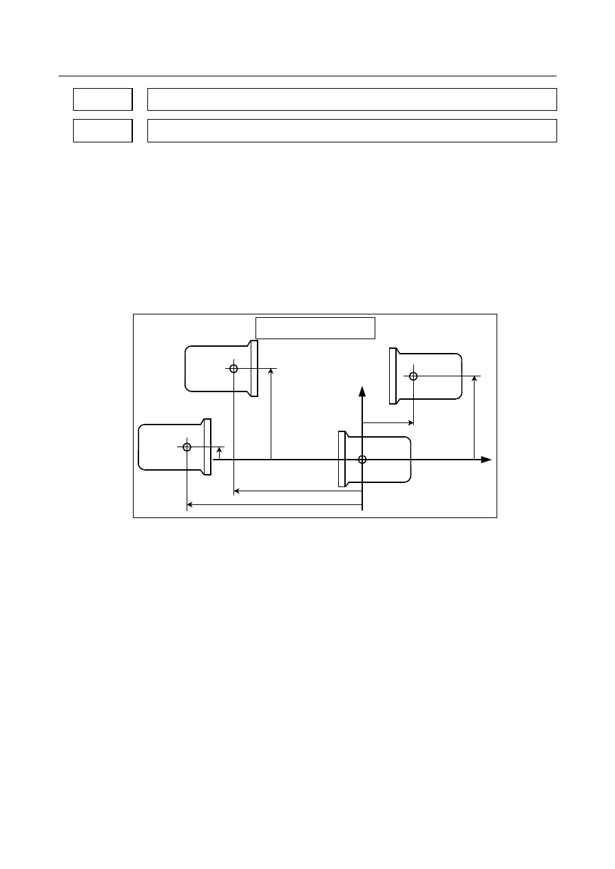
For the lathe system, only a Z-X coordinate system based on parameters Nos. 8141 and 
8143 is used for setting. 


Tool post 4 

Tool post 3 

Tool post 2 

The  tool post of path 1 in the 
same  machine  group is used as 
the reference tool post. 

+X 

+Z 

ζ

1


ε

1


ε

3


Paths in the same machine group 

ε

2


ζ

3


ζ

2


Tool post 1 

Reference 
position 

Reference 
position 

Reference 
position 

Reference 
position 


Fig. 8.4 (n) 

 
In the example above (Fig. 8.4 (n), the same machine group contains tool posts for four 
paths. In the ZX plane coordinate system with its origin placed at the reference position 
of tool post 1 of path 1 in the same machine group, the position of the reference position 
of tool post 2 of path 2 is specified by setting the value 

ε

1

  of the X component in 

parameter No. 8141 for path 2 and by setting the value 

ζ

1

  of the Z component in 

parameter No. 8143 for path 2. 
Similarly, In the ZX plane coordinate system with its origin placed at the reference 
position of tool post 1, the position  of the reference position of tool post 3 of path 3 is 
specified by setting the value 

ε

2

 of the X component in parameter No. 8141 for path 3 and 

by setting the value 

ζ

2

 of the Z component in parameter No. 8143 for path 3. In the ZX 

plane coordinate system with its origin placed at the reference position of tool post 1, the 
position of the reference position of tool post 4 of path 4 is specified by setting the value 

ε

3

 of the X component in parameter No. 8141 for path 4 and by setting the value 

ζ

3

 of the 

Z component in parameter No. 8143 for path 4. 
The unit of setting is the least input increment. For an axis based on diameter 
specification, make a setting using a diameter value. 
 

B-64693EN-1/01


8. MULTI-PATH CONTROL


- 1307 - 

  WARNING 


Measure (

ε

1

ζ

1

), (

ε

2

ζ

2

), and (

ε

3

ζ

3

) in the state where reference 

position return operation is completed for all axes (the tool is at the 
reference position.) 
After modifying parameters Nos. 8141 and 8143 for each path, be 
sure to perform a reference position return operation along all axes 
in all paths. Otherwise, the internally stored positional relationships 
of the tool posts are not updated to the newly set parameter values. 


8151 


Distance along the X axis between the reference positions of tool posts 1 and 2 


8152 


Distance along the Z axis between the reference positions of tool posts 1 and 2 


[Input type]  Parameter input 


[Data type]  Real 


[Unit of data]  mm, inch (machine unit) 

[Min. unit of data]  Depend on the increment system of the applied axis 
[Valid data range]  9 digit of minimum unit of data (refer to standard parameter setting table (A)) 

(When the increment system is IS-B, -999999.999 to +999999.999) 
These parameters are used for checking the interference between two paths when bit 7 
(IPF) of parameter No. 8140 is set to 0. 
Each of these parameters sets the distance between the tool posts of two paths. 


Tool post 2 

Tool post 1 

+X 

+Z 

ζ


ε


In the Z-X plane coordinate  system  with its origin at the reference  position  of  tool 
post  1, set the X component value 

ε

  of the reference position  of  tool post  2 in 

parameter No. 8151 and set the Z component value 

ζ

 in parameter No. 8152.


Reference 
position 

Reference 
position 


Fig. 8.4 (o) 


  WARNING 


After modifying the parameter values, perform a manual reference 
position return operation for both tool posts. Otherwise, the 
internally stored positional relationships of the two tool posts are 
not updated to the newly set parameter values. 


8. MULTI-PATH CONTROL


B-64693EN-1/01


- 1308 - 

8158 


Coordinate system pattern with the reference position based on the tool post of path 1 in the same 

machine group 


[Input type]  Parameter input 


[Data type]  Byte path 

[Valid data range]  0 to 3 

This parameter is used for checking the interference among multiple paths when bit 7 
(IPF) of parameter No. 8140 is set to 1. 
This parameter sets a coordinate system pattern with the reference position based on the 
tool post of path 1 in the same machine group. 


<1>  When the parameter No. 

8158 is set to 0 

Tool post 

+X 

+Z 

<3>  When the parameter No. 

8158 is set to 2 


Tool post 

+X 

+Z 

Tool post 

<2>  When the parameter No. 

8158 is set to 1 


+X 

+Z 

<4>  When the parameter No. 

8158 is set to 3 


Tool post 

+X 

+Z 


Fig. 8.4 (p) 


Alarm and message 

Number 

Message 

Description 

PS0169 

ILLEGAL TOOL GEOMETRY DATA 

Incorrect tool figure data in interference check. Set correct 
data, or select correct tool figure data. 

OT0508 

INTERFERENCE:+ 

A tool moving in the positive direction along the n axis has 
fouled another tool post. 

OT0509 

INTERFERENCE:- 

A tool moving in the negative direction along the n axis has 
fouled another tool post. 

Alarms will occur individually for the axes associated with interference. 
 

WARNING 

  WARNING 


After setting parameters for the interference check function, tool figure data 
(contact prohibited area), etc., be sure to enter manual mode (parameter 
settings must be such that an interference check is enabled even in manual 
mode), let the tool post of each path interfere in all directions and confirm that a 
normal interference area has been set. 


B-64693EN-1/01


8. MULTI-PATH CONTROL


- 1309 - 

8.5 

BALANCE CUTTING 

T


Overview 

When a thin workpiece is to be machined as shown below, a precise machining can be achieved by 
machining each side of the workpiece with a tool simultaneously; this function can prevent the warpage 
of the workpiece that can result when only one side is machined at a time (see the Fig. 8.5 ). When both 
sides are machined at the same time, the movement of one tool must be in phase with that of the other tool. 
Otherwise, the workpiece can vibrate, resulting in poor machining. With this function, the movement of 
one tool post can be easily synchronized with that of the other tool post. 


Tool post 1 

Tool post 2 


Fig. 8.5   

 
Specifying G68, which turns balance cutting mode on, causes balance cutting to be performed with the 
tool post of path 1 and that of path 2. Alternatively, specifying address P in the same block as that 
containing the G64 command causes balance cutting to be performed between any tool posts. 
Address P to be specified in the same block as G68, which turns balance cutting mode on can be set in 
either of two ways: 

When the bit 1 (MWP) of parameter No. 8103 is set to 0 : 


Balance cutting with a binary value specification 

When the bit 1 (MWP) of parameter No. 8103 is set to 1 : 


Balance cutting with a path number combination specification 


NOTE 

1  Balance cutting is not performed in dry run or machine lock state. G68 or G69 

specified for one tool post is synchronized with G68 or G69 specified for the 
other tool post, however. 

2  In the balance cut mode, G68 specified for one tool post is not synchronized with 

G68 specified for the other tool post. In the balance cut cancel mode, G69 
specified for one tool post is not synchronized with G69 specified for the other 
tool post. 

3  Balance cutting is not performed in a block in which 0 is specified for the travel 

distance. 

4  Balance cutting is not performed when rapid traverse is specified. 


  - 

Balance cut specified with binary values 

When bit 1 (MWP) of parameter No. 8103 is set to 0, the value specified at address P is assumed to be 
obtained using binary values. The Table 8.5 (a) lists the path numbers and corresponding binary values. 

8. MULTI-PATH CONTROL


B-64693EN-1/01


- 1310 - 

Table 8.5 (a) 

Path number 

Binary value (decimal number) 

Path number 

Binary value (decimal number) 

32 

64 

128 

256 

16 

10 

512 

 
The bit position of each path in binary representation is shown below. 

15 

14 

13 

12 

11 

10 


Path 1( 2

= 1 ) 


Path 2( 2

= 2 ) 


Path 3( 2

= 4 ) 


Path 4( 2

= 8 ) 


To perform balance cutting for all of paths 1, 2, and 3, the P value is obtained as follows: 
Binary value of path 1 

1 (0000 0000 0000 0001) 

Binary value of path 2 

2 (0000 0000 0000 0010) 

Binary value of path 3 

4 (0000 0000 0000 0100) 


Sum  


7 (0000 0000 0000 0111) 

 
Balance cutting can be performed for all of the five paths by specifying P341 together with the balance 
cut G code (G68). 
 

  - 

Balance cut specified with a combination of path numbers 

When bit 1 (MWP) of parameter No. 8103 is set to 1, the value specified at address P is assumed to be a 
combination of path numbers. The Table 8.5 (b) lists the path numbers and corresponding values. 
 

Table 8.5 (b) 

Path number 

Value (decimal number) 

Path number 

Value (decimal number) 

10 

 
To perform balance cutting for all of paths 1, 2, and 3, the P value is a number consisting of 1, 2, and 3. 
Example) P123 
There are no restrictions on the order in which the numeric characters are specified, the following six 
possible values can be specified: 

P123, P132, P213, P231, P312, P321 

Path numbers specified in combination in different orders for different paths are effective as long as the 
numbers of the relevant paths are specified. 
Example) 
 

The following are treated as the same P value 


M200P123 for path 1, M200P231 for path 2, and M200P321 for path 3 


B-64693EN-1/01


8. MULTI-PATH CONTROL


- 1311 - 

Program example 

  - 

When the value specified at P is obtained using binary values 

Programs O100, O200, and O300 for individual paths are executed as follows: 

O0300;

.

.

.

.

.

.

.

.

G68 P5; ..................... <2>

G01 X    Z    F    ;

.

.

G69;........................... <2>'

.

.

G68 P7; ..................... <3>

G01 X    Z    F    ;

.

.

G69;........................... <3>'

O0100;

.

G68 P3;...................... <1>

G01 X    Z    F    ;

.

.

G69; ........................... <1>'

.

.

G68 P5;...................... <2>

G01 X    Z    F    ;

.

.

G69; ........................... <2>'

.

.

G68 P7;...................... <3>

G01 X    Z    F    ;

.

.

G69; ........................... <3>'

O0200;

.

G68 P3; ..................... <1>

G01 X    Z    F    ;

.

.

G69; ........................... <1>'

.

.

.

.

.

.

.

.

.

.

G68 P7; ..................... <3>

G01 X    Z    F    ;

.

.

G69; ........................... <3>'

Path 1

Path 2

Path 3


<1>  G68 P3; (balance cut for paths 1 and 2) 
 

Performs balance cutting for paths 1 and 2. 


Balance cutting is performed according to the cutting feed commands between <1> and <1>'. 

<2>  G68 P5; (balance cut for paths 1 and 3) 
 

Performs balance cutting for paths 1 and 3. 


Balance cutting is performed according to the cutting feed commands between <2> and <2>'. 

<3>  G68 P7; (balance cut for paths 1, 2, and 3) 
 

Performs balance cutting for paths 1, 2, and 3. 


Balance cutting is performed according to the cutting feed commands between <3> and <3>'. 


  - 

When the value specified at P is obtained using path numbers in combination 

Programs O100, O200, and O300 for individual paths are executed as follows: 

8. MULTI-PATH CONTROL


B-64693EN-1/01


- 1312 - 

O0300;

.

.

.

.

.

.

.

.

G68 P13; ................... <2>

G01 X    Z    F    ;

.

.

G69;........................... <2>'

.

.

G68 P123; ................. <3>

G01 X    Z    F    ;

.

.

G69;........................... <3>'

O0100;

.

G68 P12; ................... <1>

G01 X    Z    F    ;

.

.

G69; ........................... <1>'

.

.

G68 P13; ................... <2>

G01 X    Z    F    ;

.

.

G69; ........................... <2>'

.

.

G68 P123;

<3>

G01 X    Z    F    ;

.

.

G69; ........................... <3>'

O0200;

.

G68 P12; ................... <1>

G01 X    Z    F    ;

.

.

G69; ........................... <1>'

.

.

.

.

.

.

.

.

.

.

G68 P123; ................. <3>

G01 X    Z    F    ;

.

.

G69; ........................... <3>'

Path 1

Path 2

Path 3


<1>  G68 P12; (balance cut for paths 1 and 2) 
 

Performs balance cutting for paths 1 and 2. 


Balance cutting is performed according to the cutting feed commands between <1> and <1>'. 

<2>  G68 P13; (balance cut for paths 1 and 3) 
 

Performs balance cutting for paths 1 and 3. 


Balance cutting is performed according to the cutting feed commands between <2> and <2>'. 

<3>  G68 P123; (balance cut for paths 1, 2, and 3) 
 

Performs balance cutting for paths 1, 2, and 3. 


Balance cutting is performed according to the cutting feed commands between <3> and <3>'. 


Parameter 


#7 

#6 

#5 

#4 

#3 

#2 

#1 

#0 

8103 


MWP 


[Input type]  Parameter input 


[Data type]  Bit 


NOTE 


When this parameter is set, the power must be turned off before 
operation is continued. 


#1  MWP

  To specify a P command for the waiting M code/balance cut: 

0: 

A binary value is used as conventionally done. 

1: 

A path number combination is used. 


B-64693EN-1/01


8. MULTI-PATH CONTROL


- 1313 - 

Caution 

  CAUTION 

1  Balance cuting only starts cutting feed on both tool posts at the same time; it 

does not maintain synchronization thereafter. To synchronize all the movements 
of both tool posts, the setting for both tool posts, such as the travel distance and 
feedrate, must be the same. Override and interlock can be applied independently 
to both tool posts. The settings for both tool posts that are related to override 
and interlock must also be the same to perform balance cutting. 

2  After feed hold is applied during execution of balance cutting for both tool posts, 

balance cutting is not performed at the restart. Balance cutting is performed 
when the next move command is executed for both tool posts. 


Note 

NOTE 

1  Time delay before the pulse distribution of both tool posts is started is 2 msec or 

shorter. 

2  Overlap is invalid. In the balance cut mode, synchronization is established at the 

start of each move block in which cutting is specified, so movement can 
momentarily stop. 

3  In the balance cut mode, continuous thread cutting overlap is also invalid. 

Perform continuous thread cutting in the balance cut cancel mode. 

4  To establish synchronization at the start of pulse distribution in a block in which 

thread cutting is specified, the same PC must be selected. 

5  The cancel mode (G69) is unconditionally set by a reset. 
6  When the mirror image for double turrets is selected, the balance cut function 

cannot be used. 


Alarm and message 

Number 

Message 

Description 

PS0163 

ILLEGAL COMMAND IN G68/G69 

G68 and G69 are not independently commanded in balance cut. 
An illegal value is commanded in a balance cut combination 
(address P).   


Content      ..     167      168      169      170     ..