FANUC Series 0i-MODEL F Plus. CONNECTION MANUAL (FUNCTION) - page 156
 

  Index      Manuals     FANUC Series 0i-MODEL F Plus. CONNECTION MANUAL (FUNCTION) B-64693EN-1/01


Search            copyright infringement  


Content      ..     154      155      156      157     ..


FANUC Series 0i-MODEL F Plus. CONNECTION MANUAL (FUNCTION) - page 156


B-64693EN-1/01


- 1202 - 

7. FEEDRATE CONTROL/ACCELERATION AND 

DECELERATION CONTROL 

7.2.5 

Optimum Torque Acceleration/Deceleration 

Overview 

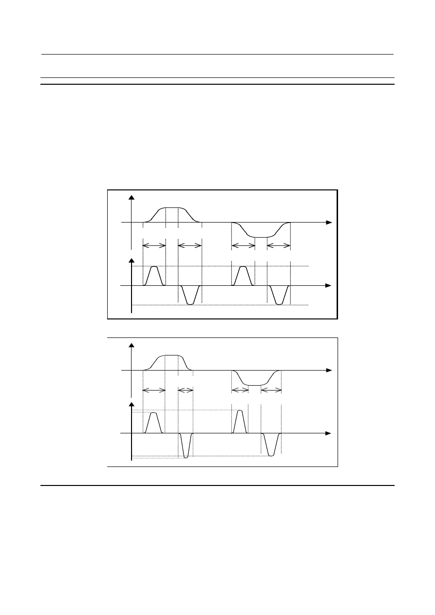
This function enables acceleration/deceleration in accordance with the torque characteristics of the motor 
and the characteristics of the machines due to its friction and gravity. 
Usually, because of the friction of the machine, gravity, the torque characteristics of the motor, and other 
factors, the acceleration/ deceleration performance (torque for acceleration/deceleration) is different with 
direction of movement, acceleration or deceleration. In this function, acceleration pattern of rapid traverse 
for the following situations, plus movement and acceleration, plus movement and deceleration, minus 
movement and acceleration, minus movement and deceleration can be set into parameters according to the 
torque for acceleration/deceleration of each situation. Acceleration/deceleration can be performed 
according to these parameter setting, so that the most of the capability of the motor can be used and 
positioning time can be reduced. 


Time 

Time 

Acceleration 

Acc/Dec pattern is the same way in each condition. 

Speed 

Acceleration 

and 

+ move 

Deceleration 

and 

+ move 


Acceleration 

and 

- move 

Deceleration 

and 

- move 


Fig. 7.2.5 (a) Conventional acceleration/deceleration 


Time 

Speed 

Time 

Acceleration 

Acceleration 

and 

+ move 

Deceleration 

and 

+ move 


Acc/Dec pattern can be changed in each condition. 

Acceleration 

and 

- move 

Deceleration 

and 

- move 


Fig. 7.2.5 (b) Acceleration/deceleration with this function 


Explanation 

Optimum torque acceleration/deceleration selects the acceleration pattern set with parameters on the basis 
of the axial movement direction and the acceleration/deceleration state, determines the acceleration for 
each axis from the current speed, and controls the tangential acceleration/deceleration for rapid traverse. 
 

  - 

Setting optimum torque acceleration/deceleration 

When bit 0 (FAP) of parameter No. 19540 and bit 1 (LRP) of parameter No. 1401 are set to 1, and a value 
other than 0 is set for any one of the axes as the reference acceleration in parameter No. 1671 as shown in 
the Fig. 7.2.5 (a), rapid traverse is accelerated/decelerated by optimum torque acceleration/deceleration. 

B-64693EN-1/01


- 1203 - 

7. FEEDRATE CONTROL/ACCELERATION 

AND DECELERATION CONTROL 

Table 7.2.5 (a) Optimum torque acceleration/deceleration 

Bit 0 (FAP) of parameter No. 

19540 

(Optimum torque acc/dec) 

Bit 1 (LRP) of parameter 

No. 1401 

(Linear type positioning) 

Reference 

acceleration 

Bell-shaped 

acceleration 
change time 

Acceleration pattern 

No.1671 

No.1672 

See "Setting an 
acceleration pattern". 

To enable bell-shaped acceleration/deceleration in addition to optimum torque acceleration/deceleration, 
set the bell-shaped acceleration change time with parameter No. 1672. 
 

NOTE 


To use optimum torque acceleration/deceleration, set bit 5 (FRP) of parameter 
No. 19501 to 1. 


  - 

Required conditions in addition to parameter setting 

If the conditions for performing AI contour control and for look-ahead  acceleration/deceleration before 
interpolation are satisfied, optimum torque acceleration/deceleration is performed for accelerating and 
decelerating rapid  traverse. However, when bit 0 (FAE) of parameter No. 11240 is set to 1, optimum 
torque acceleration/deceleration is enabled even if AI contour control is disabled. If rapid traverse is 
subject to optimum torque acceleration/deceleration, after-interpolation acceleration/deceleration does not 
apply to rapid traverse. 
 

  - 

Cases in which optimum torque acceleration/ deceleration is disabled 

If optimum torque acceleration/deceleration is disabled by parameter settings, or the required conditions 
other than parameter settings are not satisfied, acceleration/deceleration after interpolation is used to 
accelerate and decelerate rapid traverse. 
 

  - 

Setting acceleration pattern data 


Acceleration 

Speed 

Fb 

Fa 

Aa 

P1 

P2 

P3 

P4 

P5 

Ab 

Acceleration pattern 

P0 


Fig. 7.2.5 (c) Setting acceleration pattern 

 
Set the speed and the acceleration at each of the acceleration setting points P0 to P5 for each condition, 
plus movement and acceleration, plus movement and deceleration, minus movement and acceleration, 
minus movement and deceleration, and for each axis. 
The line joining the acceleration setting points is regarded a acceleration pattern. 
For example, while the speed is between Fa and Fb in the Fig. 7.2.5 (c), the acceleration is calculated with 
Aa and Ab. Tangential acceleration is controlled not to exceed the calculated acceleration for each axis.


B-64693EN-1/01


- 1204 - 

7. FEEDRATE CONTROL/ACCELERATION AND 

DECELERATION CONTROL 

NOTE 


It is not desirable to set an acceleration pattern in which a large acceleration is 
set right at a speed of 0, because this will shock the machine. So, 

be sure to set 

an acceleration pattern so that a relatively low acceleration rate is applied 
at speed 0

 as shown Fig. 7.2.5 (c). 


Table 7.2.5 (b) Parameters for acceleration pattern   

Acceleration 
setting point 

Speed 

parameter 

Acceleration parameter 

During acceleration 

During deceleration 

During 

movement in 

plus direction 

During 

movement in 

minus direction 

During 

movement in 

plus direction 

During 

movement in 

minus direction 

P0 

(Speed 0) 

No.19545 

No.19551 

No.19557 

No.19563 

P1 

No.19541 

No.19546 

No.19552 

No.19558 

No.19564 

P2 

No.19542 

No.19547 

No.19553 

No.19559 

No.19565 

P3 

No.19543 

No.19548 

No.19554 

No.19560 

No.19566 

P4 

No.19544 

No.19549 

No.19555 

No.19561 

No.19567 

P5 

No.1420 

No.19550 

No.19556 

No.19562 

No.19568 

 
The speed at P0 is 0, and the speed at P5 is the rapid traverse rate specified with parameter No. 1420. The 
speeds at P1 to P4 are to be set into speed parameters Nos. 19541 to 19544 as ratio to the rapid traverse 
speed (parameter No. 1420). 
Any acceleration setting point for which the speed parameter (one of Nos. 19541 to 19544) is set to 0 will 
be skipped, and the next point whose speed parameter is set to a non-zero value will be joined together 
connected with line. The polygonal line is regarded as acceleration pattern. 
The accelerations at P0 to P5 are to be set into acceleration parameters Nos. 19545 to 19568 as ratio to the 
reference acceleration. If any of the acceleration parameters Nos. 19545 to 19568 is set to 0, the 
acceleration is assumed 100% (Reference acceleration). Acceleration parameters should be set to 0 at the 
acceleration setting point whose speed parameter is set to 0. 
If this function is enabled and parameter No. 1671 for an axis are set to 0, the following values are 
assumed as the reference acceleration for that axis: 
  1000.0mm/sec

2

, 100.0inch/sec

2

, 100.0 degree/sec

2


  - 

Example of setting acceleration pattern data 

In this example, the machine is equipped with the 

a

i

S 30/4000. 

Motor speed at rapid traverse is 3000 (min

-1

). 

0

20

40

60

80

100

120

0

1000

2000

3000

4000

Speed(min

-1

)

T

orq

u

e

(Nm)


Fig. 7.2.5 (d) Speed-torque characteristics of model 

a

i

S 30/4000 

 
Specifications of the motor model 

a

i

S 30/4000 

Rotor inertia   

:0.0099(Kgm

2

)   

Maximum torque 

:100(Nm) 

Speed 0 to 2000(min

-1

)   

Torque at rapid traverse 

:79(Nm) 

Speed 3000(min

-1

)   

Minimum torque 

:58(Nm) 

Speed 4000(min

-1

)   


B-64693EN-1/01


- 1205 - 

7. FEEDRATE CONTROL/ACCELERATION 

AND DECELERATION CONTROL 

It assumes that 10 (Nm) is needed for the friction torque, so that the torque for acceleration/deceleration is 
shown as the following figure. 
Because the friction torque is different on each machine, it is necessary to observe the actual torque 
output on the machine for deciding acceleration pattern. 
Maximum torque 

:90(=100-10)(Nm)  Speed 0 to 2000(min

-1

)   

Torque at rapid traverse 

:69(=79-10)(Nm) 

Speed 3000(min

-1

Minimum torque 

:48(=58-10)(Nm) 

Speed 4000(min

-1

0

20

40

60

80

100

0

1000

2000

3000

4000

Speed(min

-1

)

T

orq

u

e

(Nm)


Fig. 7.2.5 (e) Torque for Acc/Dec with consideration of friction 

 
Let the torque be x (Nm), the inertia be y(Kgm

2

), and the ball screw pitch p(mm), then the acceleration A 

is calculated as follows: 

]

sec

/

[

2

]

[

2

]

[

])

][

sec

/

([

]

[

2

]

[

]

[

2

2

2

2

mm

y

p

x

mm

p

m

kg

y

m

m

kg

x

mm

p

m

kg

y

m

N

x

A

×

×

=

×

=

×

=

p

p

p


Machine specification is assumed as follows, 
Ball screw pitch  :  16 (mm)   
Inertia 


:  The machine inertia is to be 2.0 times higher than that of the rotor.   


(Rotor inertia: 0.0099 (Kgm

2

)) 

Assumption magnification as inertia of rotor and machine : 3.0 times 
According to the above equation of torque and acceleration, the acceleration at maximum torque is,   

]

sec

/

[

7717

0099

.

0

0

.

3

2

16

90

2

mm

=

×

×

×

p


The acceleration when torque 69 (Nm) at rapid traverse rate (3000 min

-1

) is, 

]

sec

/

[

5916

0099

.

0

0

.

3

2

16

69

2

mm

=

×

×

×

p


From the above data, the parameters related to acceleration pattern is given in the Table 7.2.5 (c). 
The example assumes that the torque for acceleration/deceleration is the same regardless of whether 
acceleration or deceleration is in progress or whether the movement is in the plus or minus direction. 

When setting the speed at P1, use the following value as a rough guide: 


If a bell-shaped acceleration change time (parameter No. 1672) is set, use as a rough guide the ratio 
of the following speed to the rapid traverse rate: 


Reference acceleration 

×

 T2/4 


where T2 is the bell-shaped acceleration change time (msec). 


For example, assume T2 to be 40 msec, then the speed at P1 should be approximately 


4124 [mm/sec

2

]

×

40 [msec]/4 


=4124 [mm/sec

2

]

×

602

×

40 [msec]/60000/4   


=2474 [mm/min] 

If no bell-shaped acceleration change time (parameter No. 1672) is set, use about 5% of the rapid 
traverse rate as a rough guide. 


B-64693EN-1/01


- 1206 - 

7. FEEDRATE CONTROL/ACCELERATION AND 

DECELERATION CONTROL 

Table 7.2.5 (c) Example of setting parameters related to acceleration pattern   


Parameter 

number 

Setting 

Unit 

Remarks 

Rapid traverse 
rate 

1420 

48000. 

mm/min 

The ball screw pitch is assumed 16 mm, so that 
the rapid traverse rate is 48000 mm/min at the 
maximum speed 3000 (min

-1

). 

Reference 
acceleration 

1671 

4124. 

msec 

Reference acceleration is 4124mm/sec

2

Speed at P1 

19541 

515 

0.01% 

-  Assuming that parameter No. 1672 (bell-shaped 

acceleration change time) is set to 40 (msec), 
the speed at P1 will be 2474 mm/min from the 
calculation described on the previous page. Set 
its ratio to the rapid traverse rate, or 5.15%. 


0.0515=2474/48000 

-  If parameter No. 1672 (bell-shaped acceleration 

change time) is not set, set about 5.00%. 

Speed at P2 

19542 

6666 

0.01% 

Since the torque characteristic is constant (90 Nm) 
in speeds reaching 2000 min

-1

, set P2 to the ratio 

of the speed (32000 mm/min) at 2000 min

-1

 to the 

rapid traverse rate (48000 mm/min). 
0.6666=32000 / 48000 

Speeds at P3 to 
P4 

19543 to 19544 

0.01% 

P3 to P4 are skipped because the torque drops 
almost linearly from the speed   
2000 (min

-1

) to 3000 (min

-1

). 

Acceleration at 
P0 

19545,19551, 
19557,19563 

9356 

0.01% 

Set half the acceleration at P1, or 9356. 

Acceleration at 
P1 

19546,19552, 
19558,19564 

18712 

0.01% 

At P1, 90(Nm) can be used for the 
acceleration/deceleration, so set the ratio of the 
acceleration at 90 (Nm) to the reference 
acceleration. 
(1.8712 = 7717/4124) 

Acceleration at 
P2 

19547,19553 
19559,19565 

18712 

0.01% 

At P2, set the same speed as that at P1. 

Acceleration at 
P3 to P4 

19548 to 19549, 
19554 to 19555, 
19560 to 19561 
19566 to 19567 

0.01% 

0 is set because P3 to P4 are skipped. 

Acceleration at 
P5 

19550,19556 
19562,19568 

14345 

0.01% 

At P5, 69(Nm) can be used for the 
acceleration/deceleration, so set the ratio of the 
acceleration at 69 (Nm) to the reference 
acceleration. 
(1.4345 = 5916 / 4124) 

 
With the above parameter settings, the acceleration pattern will be shown as the Fig. 7.2.5  (f). From 
speeds from 0 mm/min to 2474 mm/min, the acceleration as calculated in accordance with the 
acceleration pattern is applied; from speeds from 2474 mm/min to 32000 mm/min, an acceleration of 
7716 mm/sec

2

; and from speeds from 32000 mm/min to 48000 mm/min, the acceleration as calculated in 

accordance with the acceleration pattern. 

B-64693EN-1/01


- 1207 - 

7. FEEDRATE CONTROL/ACCELERATION 

AND DECELERATION CONTROL 

P2

P1

P0

0

1000

2000

3000

4000

5000

6000

7000

8000

9000

0

8000

16000

24000

32000

40000

48000

Speed mm/min

A

ccel

er

at

io

n m

m

/s

ec

2

P5


Fig. 7.2.5 (f) Acceleration pattern with consideration of friction 


NOTE 


The values in the model 

a

i

S 30/4000 speed-torque characteristic diagram are 

just typical ones. The values will change depending on the digital servo software, 
parameters, input voltage, and other factors. 


The optimum acceleration will, therefore, change due to the characteristics of the 
machine. 


  - 

Examples of setting if the torque of acceleration/deceleration differs 
depending on whether acceleration or deceleration is in progress and whether 
the movement is in the plus or minus direction 

From the effect of gravity and friction, torque for acceleration/deceleration is different on each condition, 
such as acceleration, deceleration or plus move (up), minus move (down). 
The following example is for the vertical axis and gravity and friction torque are assumed as follows. 
Torque of gravity : 20 (Nm) 
Torque of friction : 10 (Nm) 
Because these value are different on each machine, it is necessary to observe the output torque on the 
actual machine for deciding acceleration pattern.   
The conditions are the same as the previous example. 
(Condition) 
Motor speed at rapid traverse 

: 3000(min

-1

Ball screw pitch 

: 16(mm) 

Inertia 


: The machine inertia is to be 2.0 times higher than that of the rotor.   

Rotor inertia   

: 0.0099(Kgm

2

)   

Maximum motor torque 

: 100(Nm) Speed 0 to 2000(min

-1

)   

Motor torque at rapid traverse  : 79(Nm) 

Speed 3000(min

-1

)   

Minimum motor torque 

: 58(Nm) 

Speed 4000(min

-1

)   

 
(1)  In case of plus move (up) and acceleration 
 

Because torque of Gravity and friction work against the output torque of motor, the torque for 
acceleration/deceleration is as follows. 
Maximum torque 

: 70(=100-20-10) (Nm)   

Speed 0 to 2000(min

-1

)   

Torque at rapid traverse 

: 49(=79-20-10) (Nm)   

Speed 3000(min

-1

)   

Minimum torque 

: 28(=58-20-10) (Nm)   

Speed 4000(min

-1

)   


B-64693EN-1/01


- 1208 - 

7. FEEDRATE CONTROL/ACCELERATION AND 

DECELERATION CONTROL 

0

20

40

60

80

0

1000

2000

3000

4000

Speed(min

-1

)

T

orq

u

e

(Nm)

P0

P1

P5


Fig. 7.2.5 (g) Torque for Acc/Dec in case of + move and acceleration with   

consideration of gravity and friction. 


Parameter setting is as follows, 

Fig.7.2.5 (d)   


Parameter 

number 

Setting 

Unit 

Remarks 

Acceleration at P0 

19545 

7277 

0.01% 

Set half the acceleration at P1, or 7277. 

Acceleration at 
P1-P2 

19546,19547 

14554 

0.01% 

At P1 and P2, 70(Nm) can be used for the 
acceleration/ deceleration, so set the ratio of the 
acceleration at 70 (Nm) to the reference 
acceleration. 
  (1.4554 = 6002 / 4124) 

Acceleration at 
P3-P4 

19548 to 19549 

0.01% 

0 is set because P3 to P4 are skipped. 

Acceleration at P5 

19550 

10187 

0.01% 

At P5, 49(Nm) can be used for the 
acceleration/deceleration, so set the ratio of the 
acceleration at 49 (Nm) to the reference 
acceleration. 
(1.0187 = 4201 / 4124) 


P0

P1

P2

0

1000

2000

3000

4000

5000

6000

7000

0

8000

16000

24000

32000

40000

48000

Speed mm/min

A

ccel

er

at

io

n m

m

/s

ec

2

P5


Fig. 7.2.5 (h) Acceleration pattern in case of + move and acceleration with   

consideration of gravity and friction. 

 
(2)  In case of plus move (up) and deceleration 
 

Because torque of Gravity and friction work forward to the output torque of motor, the torque for 
acceleration/deceleration is as follows. 
Maximum torque 

:  130(=100+20+10) (Nm)   


Speed 0 to 2000(min

-1

)   

Torque at rapid traverse 

:  109(=79+20+10) (Nm)   


Speed 3000(min

-1

)   

Minimum torque 

:  88(=58+20+10) (Nm)   


Speed 4000(min

-1

)   

B-64693EN-1/01


- 1209 - 

7. FEEDRATE CONTROL/ACCELERATION 

AND DECELERATION CONTROL 

0

50

100

150

0

1000

2000

3000

4000

Speed(min

-1

)

T

orq

u

e

(Nm)

P0

P1

P5


Fig. 7.2.5 (i) Torque for Acc/Dec in case of + move and deceleration with   

consideration of gravity and friction. 


Parameter setting is as follows, 

Fig.7.2.5 (e)   


Parameter 

number 

Setting 

Unit 

Remarks 

Acceleration at 
P0 

19557 

13514 

0.01% 

Set half the acceleration at P1, or 13514. 

Acceleration at 
P1-P2 

19558, 19559 

27027 

0.01% 

At P1 and P2, 130(Nm) can be used for the 
acceleration/ deceleration, so set the ratio of the 
acceleration at 130 (Nm) to the reference 
acceleration. 
(2.7027 = 11146 / 4124) 

Acceleration at 
P3-P4 

19560 to 19561 

0.01% 

0 is set because P3 to P4 are skipped. 

Acceleration at 
P5 

19562 

22662 

0.01% 

At P5, 109(Nm) can be used for the 
acceleration/deceleration, so set the ratio of the 
acceleration at 109 (Nm) to the reference 
acceleration. 
(2.2662 = 9346 / 4124) 


P0

P1

P2

0

2000

4000

6000

8000

10000

12000

0

8000

16000

24000

32000

40000

48000

Speed mm/min

A

ccel

er

at

io

n m

m

/s

ec

2

P5


Fig. 7.2.5 (j) Acceleration pattern in case of + move and deceleration with   

consideration of gravity and friction. 

 
(3)  In case of minus move (down) and acceleration 
 

Because torque of Gravity works forward to the output torque of motor and torque of friction works 
against the output torque of motor, torque for acceleration/deceleration is as follows. 
Maximum torque 

:  110(=100+20-10) (Nm)   


Speed 0 to 2000(min

-1

Torque at rapid traverse 

:  89(=79+20-10) (Nm)   


Speed 3000(min

-1

Minimum torque 


:  68(=58+20-10) (Nm)   


Speed 4000(min

-1


Content      ..     154      155      156      157     ..