FANUC Series 0i-MODEL F Plus. CONNECTION MANUAL (FUNCTION) - page 157
 

  Index      Manuals     FANUC Series 0i-MODEL F Plus. CONNECTION MANUAL (FUNCTION) B-64693EN-1/01


Search            copyright infringement  


Content      ..     155      156      157      158     ..


FANUC Series 0i-MODEL F Plus. CONNECTION MANUAL (FUNCTION) - page 157


B-64693EN-1/01


- 1210 - 

7. FEEDRATE CONTROL/ACCELERATION AND 

DECELERATION CONTROL 

0

50

100

150

0

1000

2000

3000

4000

Speed(min

-1

)

T

orq

u

e

(Nm)

P0

P1

P5


Fig. 7.2.5 (k) Torque for Acc/Dec in case of - move and acceleration with   

consideration of gravity and friction. 


Parameter setting is as follows, 

Fig.7.2.5 (f)   


Parameter 

number 

Setting 

Unit 

Remarks 

Acceleration at 
P0 

19551 

11435 

0.01% 

Set half the acceleration at P1, or 11435. 

Acceleration at 
P1-P2 

19552,19553 

22869 

0.01% 

At P1 and P2, 110(Nm) can be used for the 
acceleration/ deceleration, so set the ratio of the 
acceleration at 110 (Nm) to the reference 
acceleration. 
(2.2869 = 9431 / 4124) 

Acceleration at 
P3-P4 

19554 to 19555 

0.01% 

0 is set because P3 to P4 are skipped. 

Acceleration at 
P5 

19556 

18504 

0.01% 

At P5, 89(Nm) can be used for the 
acceleration/deceleration, so set the ratio of the 
acceleration at 89 (Nm) to the reference 
acceleration. 
(1.8504 = 7631 / 4124) 


P0

P1

P2

0

1000

2000

3000

4000

5000

6000

7000

8000

9000

10000

0

8000

16000

24000

32000

40000

48000

Speed mm/min

A

ccel

er

at

io

n m

m

/s

ec

2

P5


Fig. 7.2.5 (l) Acceleration pattern in case of - move and acceleration with   

consideration of gravity and friction. 

 
(4)  In case of minus move (down) and deceleration 
 

Because torque of Gravity works against the output torque of motor and torque of friction works 
forward to the output torque of motor, torque for acceleration/deceleration is as follows. 
Maximum torque 

90(=100-20+10) (Nm)   


Speed 0 to 2000(min

-1

)   

Torque at rapid traverse  : 

69(=79-20+10) (Nm)   


Speed 3000(min

-1

Minimum torque 

48(=58-20+10) (Nm)   


Speed 4000(min

-1

B-64693EN-1/01


- 1211 - 

7. FEEDRATE CONTROL/ACCELERATION 

AND DECELERATION CONTROL 

0

20

40

60

80

100

0

1000

2000

3000

4000

Speed(min

-1

)

T

orq

u

e

(Nm)

P0

P1

P5


Fig. 7.2.5 (m) Torque for Acc/Dec in case of - move and deceleration with   

consideration of gravity and friction. 


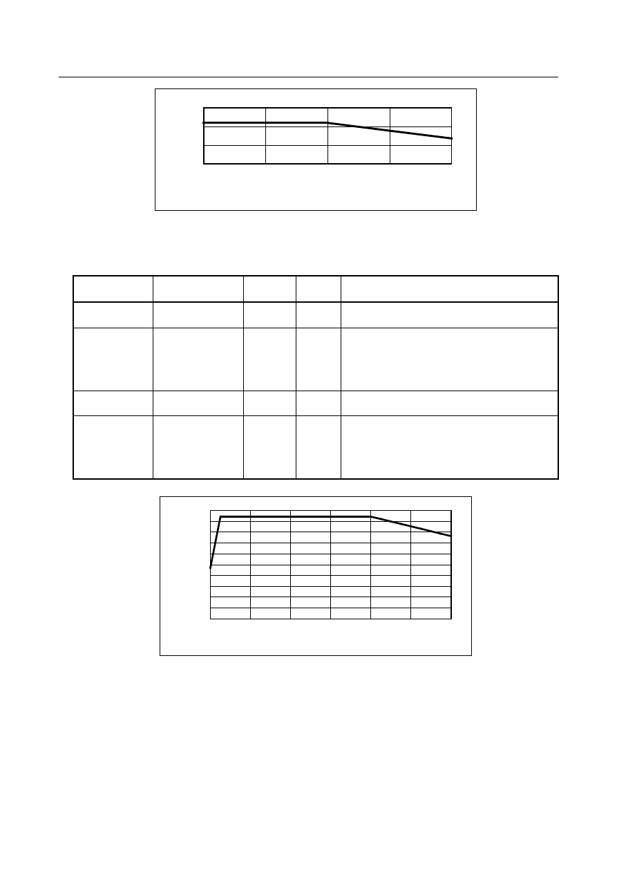
Parameter setting is as follows, 

Fig.7.2.5 (g)   


Parameter 

number 

Setting 

Unit 

Remarks 

Acceleration at 
P0 

19563 

9356 

0.01% 

Set half the acceleration at P1, or 9356. 

Acceleration at 
P1-P2 

19564,19565 

18712 

0.01% 

At P1 and P2, 90(Nm) can be used for the 
acceleration/ deceleration, so set the ratio of the 
acceleration at 90 (Nm) to the reference 
acceleration. 
  (1.8712 = 7717 / 4124) 

Acceleration at 
P3-P4 

19566 to 19567, 

0.01% 

0 is set because P3 to P4 are skipped. 

Acceleration at 
P5 

19568 

14345 

0.01% 

At P5, 69(Nm) can be used for the 
acceleration/deceleration, so set the ratio of the 
acceleration at 69 (Nm) to the reference 
acceleration. 
  (1.4345 = 5916 / 4124) 


P0

P1

P2

0

1000

2000

3000

4000

5000

6000

7000

8000

9000

0

8000

16000

24000

32000

40000

48000

Speed mm/min

A

ccel

er

at

io

n m

m

/s

ec

2

P5


Fig. 7.2.5 (n) Acceleration pattern in case of - move and deceleration with   

consideration of gravity and friction. 


Limitation 

  - 

Linear interpolation positioning 

Optimum torque acceleration/deceleration is not enabled unless linear interpolation positioning is set (bit 
1 (LRP) of parameter No. 1401 is set to 1). 
 

  - 

Valid modes and conditions 

Optimum torque acceleration/deceleration is enabled when look-ahead acceleration/deceleration before 
interpolation (AI contour control mode) is active and the conditions under which look-ahead accel-


B-64693EN-1/01


- 1212 - 

7. FEEDRATE CONTROL/ACCELERATION AND 

DECELERATION CONTROL 

eration/deceleration before interpolation is performed are satisfied (bit 1 (LRP) of parameter No. 1401 is 
set to 1, and bit  5  (FRP) of parameter  No. 19501 is set to 1, and parameter No.1671 is set to non-zero 
value). 
However, when bit 0 (FAE) of parameter No. 11240 is set to 1, optimum torque acceleration/deceleration 
is enabled even if AI contour control is disabled. 
 

  - 

Target axes 

Optimum torque acceleration/deceleration cannot be performed for a specific axis only. All axes operated 
by programmed commands are targeted for optimum torque acceleration/deceleration. This means that the 
PMC axes are excluded. 
 

  - 

Acceleration pattern 

In the same direction move, it is necessary that the acceleration during deceleration is set 1/3 of one 
during acceleration at least. 

 
Also, the acceleration pattern data must be set so that the time required for the deceleration from the rapid 
traverse rate to a speed of 0 does not exceed 4000 (msec). This does not include the acceleration change 
time of bell-shaped acceleration/deceleration. 

 
If the deceleration acceleration ratio or the time required for the deceleration to a speed of 0 exceeds the 
above range, alarm DS1710, “ILLEGAL ACC. PARAMETER (OPTIMUM TORQUE ACC/DEC)” will 
be issued at the time rapid traverse is executed. 

 
A slight error will occur between the specified acceleration and the actual acceleration. 
 

Parameter 

1671 


Maximum allowable acceleration rate in acceleration/deceleration before interpolation for linear rapid 

traverse for each axis, or allowable reference acceleration rate in optimum torque 

acceleration/deceleration 


[Input type]  Parameter input 


[Data type]  Real axis 


[Unit of data]  mm/sec

2

, inch/sec

2

, deg/sec

2

 (machine unit) 

[Min. unit of data]  Depend on the increment system of the applied axis 
[Valid data range]  Refer to the standard parameter setting table (D) 

(When the machine system is metric system, 0.0 to +100000.0. When the machine system 
is inch system, machine, 0.0 to +10000.0.) 
(1)  Set a maximum allowable acceleration rate in look-ahead acceleration/ deceleration 

before interpolation for linear rapid traverse. 


If a value greater than 100000.0, the value is clamped to 100000.0. 


If 0 is set, the specification of the following is assumed: 


  1000.0 mm/sec

2


  100.0 inch/sec

2


  100.0 degrees/sec

2


If 0 is specified  for all axes,  however,  look-ahead  acceleration/deceleration  before 
interpolation is not performed. 

(2)  Allowable reference acceleration rate in optimum torque acceleration/deceleration 
 

B-64693EN-1/01


- 1213 - 

7. FEEDRATE CONTROL/ACCELERATION 

AND DECELERATION CONTROL 

1672 


Acceleration change time of bell-shaped acceleration/deceleration before interpolation for linear rapid 

traverse, or acceleration change time of bell-shaped acceleration/deceleration in optimum torque 

acceleration/deceleration 


[Input type]  Parameter input 


[Data type]  2-word path 


[Unit of data]  msec 

[Valid data range]  0 to 200 

(1)  Set an acceleration  change time of bell-shaped  acceleration/  deceleration  for  linear 

rapid traverse (time for changing from the state of constant feedrate (A) to the state 
of constant acceleration/deceleration (C) at the acceleration rate calculated from the 
acceleration rate set in parameter No. 1671: time of (B) in the figure below). 

(2)  Set an acceleration change time of bell-shaped acceleration/ deceleration in optimum 

torque  acceleration/deceleration  (time for changing from the state  of constant 
feedrate  (A) to the state  of  acceleration/deceleration  (C) at the acceleration  rate 
calculated from optimum torque acceleration/deceleration: time of (B) in the figure). 

Feedrate in tangent direction

Maximum  acceleration rate not exceeding
maximum allowable acceleration rate set by
parameter No. 1671 for each axis is
automatically calculated.

Time set by parameter No. 1672

(A)

(B)

(B)

(B)

(B)

(A)

(A)

(C)

(C)


Fig. 7.2.5 (o) 


#7 

#6 

#5 

#4 

#3 

#2 

#1 

#0 

11240 


FAE 


[Input type]  Parameter input 


[Data type]  Bit path 


#0  FAE

  During positioning when the AI contour control mode is canceled, the optimum torque 

acceleration/deceleration is: 
0: 

Disabled. 

1: 

Enabled. 


#7 

#6 

#5 

#4 

#3 

#2 

#1 

#0 

19501 


FRP 


[Input type]  Parameter input 


[Data type]  Bit path 


#5  FRP

  Linear rapid traverse is: 

0: 

Acceleration/deceleration after interpolation 

1: 

Look-ahead acceleration/deceleration before interpolation 

Set a maximum allowable acceleration rate for each axis in parameter No. 1671. 
When using look-ahead bell-shaped acceleration/deceleration before interpolation, set an 
acceleration rate change time in parameter No. 1672. 


B-64693EN-1/01


- 1214 - 

7. FEEDRATE CONTROL/ACCELERATION AND 

DECELERATION CONTROL 

When this parameter is set to 1, look-ahead acceleration/deceleration before interpolation 
is  also applied to rapid traverse  if all conditions below are satisfied. At this time, 
acceleration/deceleration after interpolation is not applied. 

Bit 1 (LRP) of parameter No. 1401 is set to 1: Linear interpolation type positioning 

A value other than 0 is set in parameter No. 1671 for an axis. 

The AI contour control mode is set. 

If all of these conditions are not satisfied, acceleration/deceleration after interpolation is 
applied. 


#7 

#6 

#5 

#4 

#3 

#2 

#1 

#0 

19540 


FAP 


[Input type]  Parameter input 


[Data type]  Bit path 


#0  FAP

  Optimal torque acceleration/deceleration is: 

0: 

Disabled. 

1: 

Enabled. 

When the linear positioning parameters, namely bit 1 (LRP) of parameter No. 1401 and 
bit 0 (FAP) of parameter No.  19540, are set to 1, and a value  other than 0 is set in 
reference  acceleration  parameter  No. 1671 for an axis, the acceleration/deceleration  for 
rapid traverse  becomes optimal torque  acceleration/deceleration  in the mode for 
look-ahead acceleration/deceleration before interpolation (or the  AI contour control 
mode). Optimal torque acceleration/ deceleration is controlled according to parameter-set 
restricted acceleration curve data. 
 
Setting an acceleration pattern 


Acceleration 

Speed 

Fb 

Fa 

Aa 

P1 

P2 

P3 

P4 

P5 

Ab 

Acceleration pattern 

P0 


Fig. 7.2.5 (p) 

 
Set the speed at each of the acceleration  setting points (P0 to P5) in a corresponding 
parameter, then in parameters for each axis, set acceleration  rates applicable in the 
following four cases at these speeds: when a movement in the positive direction is 
accelerated, when a movement in the positive direction is decelerated, when a movement 
in the negative direction is accelerated, and when a movement in the negative direction is 
decelerated. 
The line connecting the acceleration setting points is the acceleration pattern. 
The acceleration rate for each axis is calculated. For example, between speeds Fa to Fb in 
the above figure, the acceleration rates corresponding to these speeds, Aa to Ab, are used 
for calculation. 
The tangent acceleration  is controlled so that it does not exceed the calculated 
acceleration rate for each axis. 
 

B-64693EN-1/01


- 1215 - 

7. FEEDRATE CONTROL/ACCELERATION 

AND DECELERATION CONTROL 

  CAUTION 


When an acceleration pattern is set, setting a high acceleration rate 
immediately after a speed of 0 can cause an impact on the 
machine, so it is not desirable. Therefore, 

be sure to apply a 

relatively low acceleration rate at a speed of 0

 as shown in the 

above figure. 


19541 


Optimal torque acceleration/deceleration (speed at P1) 

to 


to 

19544 


Optimal torque acceleration/deceleration (speed at P4) 


[Input type]  Parameter input 


[Data type]  Word axis 


[Unit of data]  0.01% 

[Valid data range]  0 to 10000 

The speeds at acceleration setting points P1 to P4 are to be set with speed parameters Nos. 
19541 to 19544 as ratios to the rapid traverse speed (parameter No. 1420). The speed at 
P0 is 0, and the speed at P5 is the rapid traverse rate specified with parameter No. 1420. 
Any acceleration setting point for which the speed parameter (one of Nos. 19541 to 
19544) is set to 0 will be skipped. 
 

19545 


Optimal torque acceleration/deceleration (acceleration at P0 during movement in + direction and 

acceleration) 

to 


to 

19550 


Optimal torque acceleration/deceleration (acceleration at P5 during movement in + direction and 

acceleration) 


19551 


Optimal torque acceleration/deceleration (acceleration at P0 during movement in - direction and 

acceleration) 

to 


to 

19556 


Optimal torque acceleration/deceleration (acceleration at P5 during movement in - direction and 

acceleration) 


19557 


Optimal torque acceleration/deceleration (acceleration at P0 during movement in + direction and 

deceleration) 

to 


to 

19562 


Optimal torque acceleration/deceleration (acceleration at P5 during movement in + direction and 

deceleration) 


19563 


Optimal torque acceleration/deceleration (acceleration at P0 during movement in - direction and 

deceleration) 

to 


to 

19568 


Optimal torque acceleration/deceleration (acceleration at P5 during movement in - direction and 

deceleration) 


[Input type]  Parameter input 


[Data type]  Word axis 


[Unit of data]  0.01% 

[Valid data range]  0 to 32767 

For each travel direction  and each acceleration/deceleration  operation, set the allowable 
acceleration  rate at each of the acceleration  setting  points (P0  to  P5). As an allowable 
acceleration  rate, set a ratio to the  value  set in the reference  acceleration  parameter  No. 
1671. When 0 is set, the specification of 100% is assumed. 


B-64693EN-1/01


- 1216 - 

7. FEEDRATE CONTROL/ACCELERATION AND 

DECELERATION CONTROL 

Alarm and message 

Number 

Message 

Description 

DS1710 

ILLEGAL ACC. PARAMETER 
(OPTIMUM TORQUE ACC/DEC) 

There are errors in the parameters of permissible acceleration for 
Optimum Torque Acceleration/Deceleration. 
One of the following is the cause. 
1)  The ratio of the acceleration for deceleration to the 

acceleration for the acceleration is lower than the limited 
value. 

2)  The time to decelerate to 0 is larger than the maximum. 


Reference item 

Manual name 

Item name 

OPERATOR’S MANUAL (B-64694EN) 

Optimum torque acceleration/deceleration   


7.2.6 

Corner Control 

7.2.6.1 

In-position check signal 

Overview 

On general CNCs, the feedrate during cutting feed never becomes 0 between two successive blocks. 
So, a corner may be rounded. 


This portion causes a corner 
to be rounded. 

F

eedrat

e


Time 

Program path 

Actual tool center 
path 


By using the in-position check signal, control can be exercised so that machining can proceed to the next 
block after checking that the acceleration/deceleration processing of the previous block is completed and 
the effective area has been entered. 


F

eedrat

e


Time 


B-64693EN-1/01


- 1217 - 

7. FEEDRATE CONTROL/ACCELERATION 

AND DECELERATION CONTROL 

Signal 

In-position check signal SMZ<Gn053.6> 

     [Classification]  Input signal 
 

[Function]  This signal selects whether to make an in-position check between successive cutting feed 

blocks during automatic operation. 
In general, slight rounding occurs between successive cutting feed blocks because of an 
acceleration/deceleration delay or servo delay. 
By making an in-position check (to proceed to the next block after waiting until 
acceleration/deceleration and servo delays disappear), this rounding can be eliminated. 


[Operation]  When this signal is set to "0", machining proceeds to the next block without making an 

in-position check between successive cutting feed blocks during automatic operation. 
When this signal is set to "1", machining proceeds to the next block after making an 
in-position check between successive cutting feed blocks during automatic operation. 


NOTE 


Before and after a block for positioning, an in-position check is 
made, regardless of the setting of this signal. 

(However, the setting of bit 5 (NCI) of parameter No. 1601 is 
followed.) 


Signal address 


#7 

#6 

#5 

#4 

#3 

#2 

#1 

#0 

Gn053 


SMZ 


7.2.6.2 

In-position check 

Overview 

Whether the position of the servo motor is within a specified range is checked. 
If the in-position check function is enabled, the CNC checks the position during deceleration. If the 
position is found to exceed the specified range, the CNC does not execute the next block. 
 

NOTE 

1  The purpose of in-position check is to check that the servo motor has reached 

within a specified range (specified with parameter No. 1826).   

2  In-position check is executed for all axes in the path. Therefore, the axis which is 

not commanded is also the target of in-position check. 


Signal 

In-position signals INP1 to INP8<Fn104> 

    [Classification]  Output signal 
 

  [Function]  These signals indicate that the control axes are set to the in-position condition. 

They are provided for each control axis, and the end number in the signal name 
corresponds to the control axis number. 
INPx 
x :  1 ..... The 1st axis is set to the in-position condition. 

2 ..... The 2nd axis is set to the in-position condition. 
3 ..... The 3rd axis is set to the in-position condition. 
  : 


[Output cond.]  These signals turn to "1" in the following case : 

The move command of the corresponding control axis is not specified and the servo 
error of the corresponding control axis is within the specified allowance. 


Content      ..     155      156      157      158     ..