FANUC Series 0i-MODEL F Plus. CONNECTION MANUAL (FUNCTION) - page 154
 

  Index      Manuals     FANUC Series 0i-MODEL F Plus. CONNECTION MANUAL (FUNCTION) B-64693EN-1/01


Search            copyright infringement  


Content      ..     152      153      154      155     ..


FANUC Series 0i-MODEL F Plus. CONNECTION MANUAL (FUNCTION) - page 154


B-64693EN-1/01


- 1186 - 

7. FEEDRATE CONTROL/ACCELERATION AND 

DECELERATION CONTROL 

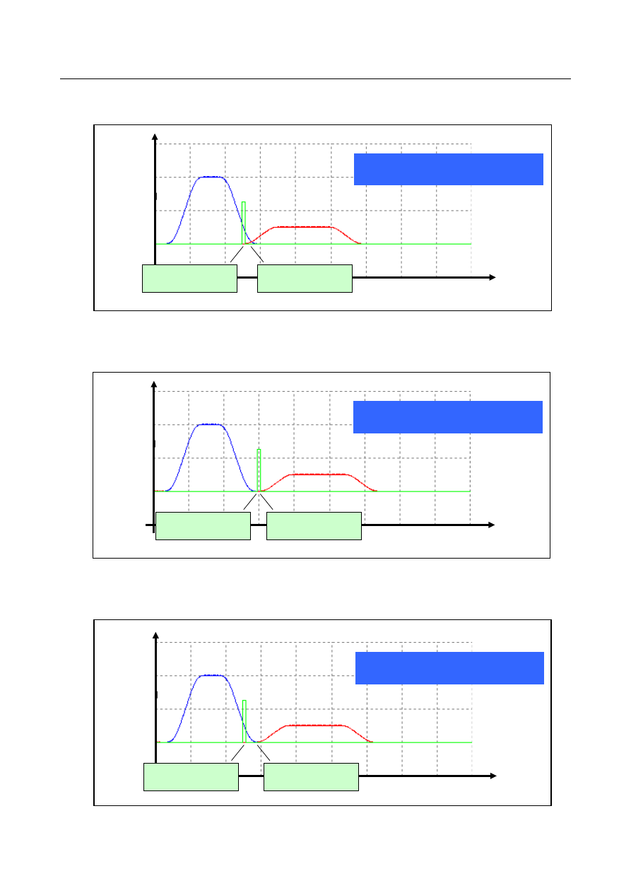
Example 4 of overlap [Rapid traverse 

 No movement (only M code) 

 Cutting feed] 


(In case that the execution time of M code is shorter than overlap time) 


Feedrate 

Rapid 

traverse 

Cutting 

feed 

Overlap enabled 

Parameter SRN=0 

Overlap enabled 

Parameter SNC=0 

Overlap is executed across 

no movement block (only M code) 

Time 

No movement 

M code 


Fig. 7.2.1.4 (i)    Example 4 of overlap 


Example 5 of overlap [Rapid traverse 

 No movement (only M code) 

 Cutting feed] 


(In case that overlap is disabled from rapid traverse block to no movement block) 


Feedrate 

Rapid 

traverse 

Cutting 

feed 

Overlap disabled 

Parameter SRN=1 

Overlap enabled 

Parameter SNC=0 

Overlap is not executed across   

no movement block (only M code)


Time 

No movement 

M code 


Fig. 7.2.1.4 (j)    Example 5 of overlap 


Example 6 of overlap [Rapid traverse 

 No movement (only M code) 

 Cutting feed] 


(In case that overlap is disabled from no movement block to cutting feed block) 


Feedrate 

Rapid 

traverse 

Cutting 

feed 

Overlap enabled 

Parameter SRN=0 

Overlap disabled 

Parameter SNC=1 

Overlap is not executed across 

no movement block (only M code) 

Time 

No movement 

M code 


Fig. 7.2.1.4 (k)    Example 6 of overlap 


B-64693EN-1/01


- 1187 - 

7. FEEDRATE CONTROL/ACCELERATION 

AND DECELERATION CONTROL 

- Relation to each function 

The relation to each function is as follows. 
 
- Rapid traverse block overlap 

Rapid traverse block overlap can be used concurrently with Smart overlap. When rapid traverse block 
overlap and Smart overlap are used at the same time, overlap is performed from the bigger of the 
overlap value specified for the two functions. 

 
- Optimum acceleration/deceleration for rigid tapping 

The function for acceleration/deceleration by Smart overlap is ineffective  in Optimum 
acceleration/deceleration for rigid tapping block. Moreover, the overlap is not performed before and 
after the block. 

 
- High precision oscillation function 

The function for acceleration/deceleration by Smart overlap is ineffective  while High precision 
oscillation function is executing. Moreover, the overlap is not performed before and after the block. 
 

- Axis synchronous control 

The function for acceleration/deceleration by Smart overlap is ineffective  while Synchronization 
establishment function is executing. Moreover, the overlap is not performed before and after the block. 

 
- PMC Axis Control 

Automatic acceleration/deceleration is ineffective while the skip command (03h) of PMC axis control 
is executing. The acceleration/deceleration by Smart overlap is ineffective too, and the overlap is not 
performed before and after the block. 
For the other commands of PMC axis control, the acceleration/deceleration by Smart overlap is 
effective, but the overlap is not performed before and after the block. 


- Function of deceleration stop in case of power failure 

The function for acceleration/deceleration by Smart overlap is ineffective while the deceleration stop in 
case of power failure is executing. Moreover, the overlap is not performed before and after the block. 

 
- Arbitrary speed threading 

The function for acceleration/deceleration by Smart overlap is ineffective  while arbitrary  speed 
threading is executing. Moreover, the overlap is not performed before and after the block. 

 
- Non-buffering block 

The acceleration/deceleration by Smart overlap is effective in the non-buffering block. However, the 
overlap is ineffective  before and after the block. In the following examples, the overlap is not 
performed between N1-N2 and between N2-N3. 

Example) 

N1 Gxx ; 
N2 Mxx ;

Non-buffering M code 

N3 Gxx ; 

 
- Automatic reference position return (G28, G30) 

The acceleration/deceleration by Smart overlap is effective in the automatic reference position return 
command. However, the overlap is ineffective  between the movement to the reference point and the 
next block. The overlap is effective between before the reference point return command block and the 
movement to the middle point. 

 
- In-position check disable reference position return (G28.2,G30.2)   

This command is similar to automatic reference point return (G28,G30). 


B-64693EN-1/01


- 1188 - 

7. FEEDRATE CONTROL/ACCELERATION AND 

DECELERATION CONTROL 

- High-speed G53 function (G53P1) 

High-speed G53 function is non-buffering G code. But, the acceleration/deceleration by Smart overlap 
is effective, and the overlap is also effective before and after the block. 

 
- Threading 

The acceleration/deceleration by Smart overlap is effective in the start block of threading (Block that 
waits for one-rotation signal). However, the overlap is ineffective between previous block. 

 
- Threading cycle 

Smart overlap is performed between "retract" and "return" and between "return" and "positioning" in 
the threading cycle. 

 
- Rigid tapping 

The acceleration/deceleration by Smart overlap is effective in the following blocks. However, the 
overlap is not performed before and after the block. 


- Movement block from I point (Initial point) to R point and movement block from R point to Z point 

(hole bottom) 

- Movement block from R point to Z point (hole bottom) and movement block from Z point (hole 
bottom) to R point. 


- Movement block from Z point (hole bottom) to R point and movement block from R point to I point 

(Initial point) 
 
- Exact Stop (G09)/Exact Stop mode (G61) 

The function for acceleration/deceleration by Smart overlap is effective  in the exact stop block. 
However, the overlap is not performed between the next block. 

 
- Synchronous/Composite control, Superimposed control 

If Smart overlap is effective even one axis, an operation equivalent to that of following setting is 
performed. 
-  Bit 5 (NCS) of parameter No.8160 is 1, bit 7 (NRS) of parameter No.8160 is 1, bit 1 (MSO) of 
parameter No.8168 is 1 

 
- In-position check 

If Smart overlap is effective even one axis, an operation equivalent to that of following setting is 
performed. 
- Bit 4 of parameter No.11503 is 1 

 
- In-position check signal 

In Smart overlap between cutting feed blocks, the in-position check signal can be switched enabled and 
disabled by the parameter SIE(No.10735#4) . 

 
- Manual operation 

Smart overlap is also effective in manual operation. 
 

- Dwell command 

Between dwell command and the previous block, overlap can be switched between enabled and 
disabled by the parameter SOD(No.10735#7). 


B-64693EN-1/01


- 1189 - 

7. FEEDRATE CONTROL/ACCELERATION 

AND DECELERATION CONTROL 

Disabling Smart overlap of rigid tap 

When Smart overlap is applied to rigid tap, the sum of the time constant of acceleration/deceleration 
after  interpolation(parameters  No.5261 to 5264, etc) in rigid tap and the time constant of 
acceleration/deceleration after interpolation(parameters Nos.11248 and 11249) in Smart overlap is the 
total time. Therefore, it is necessary to subtract the time constant  of acceleration/deceleration after 
interpolation in Smart overlap from the time constant of acceleration/deceleration after interpolation in 
rigid tap and adjust so that the total time constant of acceleration/deceleration after interpolation does 
not change. However, if the time constant of acceleration/deceleration after interpolation in rigid tap is 
less than the time constant of acceleration/deceleration after interpolation in Smart overlap, all the time 
constant of acceleration/deceleration after interpolation in Smart overlap cannot be subtracted from the 
time constant of acceleration/deceleration after interpolation in rigid tap. As a result, the total time 
constant of acceleration/deceleration after interpolation may be increased and the cycle time may be 
extended. 
 

Table 7.2.1.4 (e)    Adjustment example of time constant of acceleration/deceleration after interpolation 


Time constant of acceleration/deceleration 

after interpolation 

Total time constant of 

acceleration/deceleration 

after interpolation 

rigid tap 

Smart overlap 

Before Smart overlap 

applying 

No.5261=16 

No.5365=4 

No.11248=0 
No.11249=0 

20 

After Smart overlap 

application 

(Subtract can be done) 

No.5261=0 
No.5365=0 

No.11248=16 

No.11249=4 

20 

After Smart overlap 

application 

(Subtract cannot be done) 

No.5261=0 
No.5365=0 

No.11248=24 

No.11249=8 

32 

 
By setting bit 5 (SRI) or bit 6 (RIS) of parameter No. 10735 to 1, Smart overlap can be invalidated at the 
cutting and extraction in rigid tap. Therefore, the cycle time can be prevented being postponed in rigid 
tap. 
For each rigid tap, the parameters of time constant of acceleration/deceleration after interpolation that is 
valid and the parameters to invalidate the Smart overlap are shown in the table below. 
 

Table 7.2.1.4 (f)    Parameters effective for each rigid tap 

Type of rigid tap 

Time constant of 

acceleration/deceleration after 

interpolation 

Smart overlap invalid 

Rigid tap 

No.5261 to No.5264, 
No.5271 to No.5274, 

No.5365 to No.5368 

Parameter SRI 

Retraction for rigid tapping 

3-dimensional rigid tapping 

Retraction for 3-dimensional rigid tapping 

Rigid tapping by manual handle 

Rigid tapping of spindle control with servo 

motor 

No.11060 to No.11063, 
No.11065 to No.11068, 

No.11052 

Parameter RIS 

Rigid tapping of spindle control with Cs 

contour control 

FSSB High-speed rigid tapping 

Compliant with the base rigid tap 


NOTE 

  In synchronous control slave axis, setting of the path of the synchronous master 

axis is effective for the parameters SRI and RIS. 

  In composite control axes of composite control, setting of the path of the 

composite target axis is effective for the parameters SRI and RIS. 


B-64693EN-1/01


- 1190 - 

7. FEEDRATE CONTROL/ACCELERATION AND 

DECELERATION CONTROL 


Spindle stop 

Spindle stop, M

β

,   

Spindle stop 

Spindle CW 

P

2


Initial point 

R point 

P

1


Z(X) point 

Motion 1 

Motion 2 

Motion 3 

Motion 4 

Motion 5 


Motion 6 


M

a


G84 (G88) (G98 mode) 

Spindle stop 


Spindle CW 


Spindle CCW 


Initial point 

R point 

Z(X) point 


Motion 1 

Motion 2 


Motion 3 


Motion 4 


Motion 5 


M

a


Spindle stop, M

β

,   P

2


P

1


Rapid traverse 
Cutting feed 

P

1


Dwell specified by address P in the program 

P

2


Dwell set by parameter No. 5111 (not performed in the FANUC Series 15 program format) 


G84 (G88) (G99 mode) 

Spindle CCW 

Spindle stop 


M

a

  Output of an M code for C-axis clamping 

M

β

  Output of an M code for C-axis unclamping (

β

=

a

+1) (not performed in the FANUC Series 15 

program format) 

Supplement:  P1, M

a

, M

β

, and P2, when not specified, are not executed and output. 


When the parameter SIE or RIS is set to 0 

In motion 3 and 5, the parameters (Nos.11248 and 11249) are added to the time constant of 
acceleration/deceleration after interpolation in rigid tap.   
 

When the parameter SIE or RIS is set to 1 

In motion 3 and 5, the parameters (Nos.11248 and 11249) are not added to the time constant of 
acceleration/deceleration after interpolation in rigid tap.   


NOTE 


Even when parameters SRI and RIS are set to 1, there is no change in motion 1, 
2, 4, 6. 


B-64693EN-1/01


- 1191 - 

7. FEEDRATE CONTROL/ACCELERATION 

AND DECELERATION CONTROL 

NOTE 

NOTE 

1  Smart overlap is effective for the rigid tapping and threading, etc. Therefore, 

please confirm the screw precision. 

2  Smart overlap is effective for the skip command. Therefore, the skip coordinates 

value is influenced. So, when the accumulated pulses by 
acceleration/deceleration of Smart overlap is considered and compensated, set 
bit 1 (SEB) of parameter (No. 6201) to 1. 

3  When the overlap is executed at the block where the direction of the movement 

reverses, the direction of the movement reverses before the tool reaches the 
programmed position. In the drilling, the tool doesn't reach the programmed 
bottom of a hole. 


Parameter 


#7 

#6 

#5 

#4 

#3 

#2 

#1 

#0 

10735 


SOD 

RIS 

SRI 

SIE 


ARF 


[Input type]  Parameter input 


[Data type]  Bit path 


#0  ARF

  In Smart overlap, between movement block of reference position return to the middle 

point and previous block overlap is : 
0: 

Enabled. 

1: 

Disabled. 


#4  SIE

  In the axis that Smart overlap is effective, the in-position check signal is: 

0: 

Disabled. 

1: 

Enabled. 


NOTE 

 Smart overlap is effective between the following blocks, but the 
in-position check signal is not effective. 

-  Rapid traverse - Rapid traverse 
-  Rapid traverse - Cutting feed 
-  Rapid traverse - No movement 
-  Cutting feed - Rapid traverse 
-  Cutting feed - No movement 
-  No movement - Rapid traverse 
-  No movement - Cutting feed 
-  No movement - No movement 


#5  SRI

  In cutting and extraction in the rigid tap, Smart overlap is: 

0: 

Depending on the setting in bit 1 (SOVx) of parameter No.11236 

1: 

Disabled. 


B-64693EN-1/01


- 1192 - 

7. FEEDRATE CONTROL/ACCELERATION AND 

DECELERATION CONTROL 

NOTE 


This parameter is effective for the next rigid tap. 

-  Rigid tap 
-  Rigid tapping by manual handle 
-  3-dimensional rigid tapping 
-  Retraction for rigid tapping 
-  Retraction for 3-dimensional rigid tapping 


#6  RIS

  In cutting and extraction in the rigid tapping of spindle control with servo motor Smart 

overlap is: 
0: 

Depend on the bit 1 (SOVx) of parameter No.11236 setting. 

1: 

Disabled. 


#7  SOD

  In Smart overlap, between dwell block and previous block overlap is : 

0: 

Enabled. 

1: 

Disabled. 


10740 


Maximum overlap value of Smart overlap for each axis 

(R

apid traverse -

 R

apid traverse) 


[Input type]  Parameter input 


[Data type]  2-word axis 


[Unit of data]  Detection unit 

[Valid data range]  0 to 99999999 

The maximum clamp value of Smart overlap between the rapid traverse block and the 
rapid traverse block is set. 
The overlap value is clamped by the value set to this parameter. So, the inner deviation in 
the corner can be suppressed. 
 

NOTE 


When a value less than 0 are set, the specification of 0 is assumed.


In this case, the overlap by Smart overlap is not clamped. 
When you clamp overlap value, set the value of in-position width or 
more. 


10741 


Maximum overlap value of Smart overlap for each axis 

(R

apid traverse – Cutting feed) 


[Input type]  Parameter input 


[Data type]  2-word axis 


[Unit of data]  Detection unit 

[Valid data range]  0 to 99999999 

The maximum clamp value of Smart overlap between the rapid traverse block and the 
cutting feed block is set. 
The overlap value is clamped by the value set to this parameter. So, the inner deviation in 
the corner can be suppressed. 
 

NOTE 


When a value less than 0 are set, the specification of 0 is assumed.


In this case, the overlap by Smart overlap is not clamped. 
When you clamp overlap value, set the value of in-position width or 
more. 


B-64693EN-1/01


- 1193 - 

7. FEEDRATE CONTROL/ACCELERATION 

AND DECELERATION CONTROL 

10742 


Maximum overlap value of Smart overlap for each axis (Cutting feed - 

R

apid traverse) 


[Input type]  Parameter input 


[Data type]  2-word axis 


[Unit of data]  Detection unit 

[Valid data range]  0 to 99999999 

The maximum clamp value of Smart overlap between the cutting feed block and the rapid 
traverse block is set. 
The overlap value is clamped by the value set to this parameter. So, the inner deviation in 
the corner can be suppressed. 
 

NOTE 


When a value less than 0 are set, the specification of 0 is assumed.


In this case, the overlap by Smart overlap is not clamped. 
When you clamp overlap value, set the value of in-position width or 
more. 


#7 

#6 

#5 

#4 

#3 

#2 

#1 

#0 

11236 


SOVx 


[Input type]  Parameter input 


[Data type]  Bit axis 


NOTE 


When this parameter is set, the power must be turned off before 
operation is continued. 


#1  SOVx

  Smart overlap is 

0: 

Disabled. 

1: 

Enabled. 


#7 

#6 

#5 

#4 

#3 

#2 

#1 

#0 

11247 


SNN 

SNC 

SNR 

SCN 

SCR 

SRN 

SRC 

SRR 


[Input type]  Parameter input 


[Data type]  Bit path 


#0  SRR

  In Smart overlap, between rapid traverse block and rapid traverse block overlap is : 

0: 

Enabled. 

1: 

Disabled. 


#1  SRC

  In Smart overlap, between rapid traverse block and cutting feed block overlap is : 

0: 

Enabled. 

1: 

Disabled. 


#2  SRN

  In Smart overlap, between rapid traverse block and non-movement block overlap is : 

0: 

Enabled. 

1: 

Disabled. 


#3  SCR

  In Smart overlap, between cutting feed block and rapid traverse block overlap is : 

0: 

Enabled. 

1: 

Disabled. 


Content      ..     152      153      154      155     ..