FANUC Series 0i-MODEL F Plus. CONNECTION MANUAL (FUNCTION) - page 152
 

  Index      Manuals     FANUC Series 0i-MODEL F Plus. CONNECTION MANUAL (FUNCTION) B-64693EN-1/01


Search            copyright infringement  


Content      ..     150      151      152      153     ..


FANUC Series 0i-MODEL F Plus. CONNECTION MANUAL (FUNCTION) - page 152


B-64693EN-1/01


- 1170 - 

7. FEEDRATE CONTROL/ACCELERATION AND 

DECELERATION CONTROL 

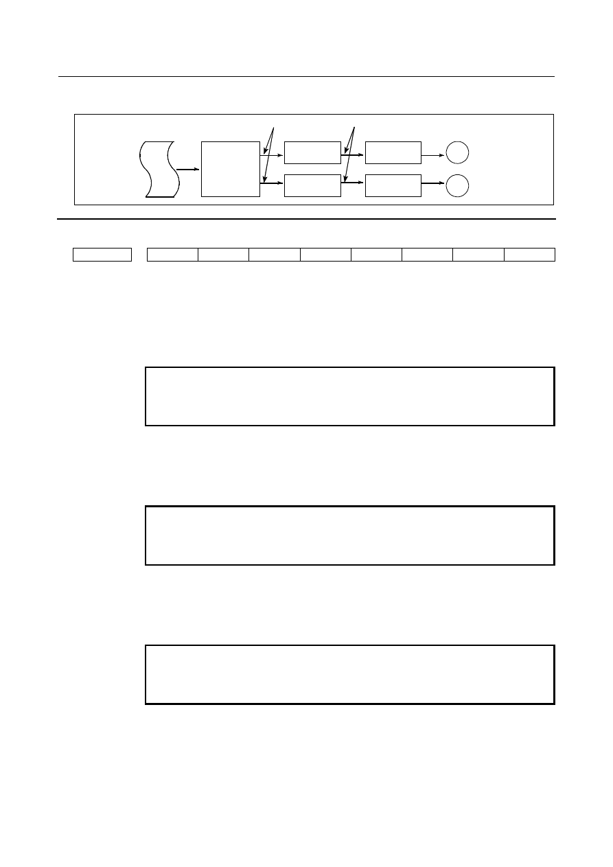
Jog feed 

:  Exponential acceleration/deceleration (time constant per axis is set by parameter No. 

1624) 


CNC 

command 


Pulse 
distribution   
(interpolation) 


Rate after interpolation 


Rate after acceleration/deceleration 


Servo motor 


Acceleration/ 

deceleration 

control 

Servo 

control 


Acceleration/ 

deceleration 

control 


Servo 

control 


Parameter 


#7 

#6 

#5 

#4 

#3 

#2 

#1 

#0 

1610 


THLx 

JGLx 


CTBx 

CTLx 


[Input type]  Parameter input 


[Data type]  Bit axis 


#0  CTLx

  Acceleration/deceleration in cutting feed or dry run during cutting feed 

0: 

Exponential acceleration/deceleration is applied. 

1: 

Linear acceleration/deceleration after interpolation is applied. 


NOTE 


This parameter is initial setting parameter. For details, refer to the 
appendix "Automatic setting / Initial setting parameter" in this 
manual. 


#1  CTBx

  Acceleration/deceleration in cutting feed or dry run during cutting feed 

0: 

Exponential acceleration/deceleration or linear acceleration/ deceleration is applied.   
(depending on the setting in bit 0 (CTLx) of parameter No. 1610) 

1: 

Bell-shaped acceleration/deceleration is applied. 


NOTE 


This parameter is initial setting parameter. For details, refer to the 
appendix "Automatic setting / Initial setting parameter" in this 
manual. 


#4  JGLx

  Acceleration/deceleration in jog feed 

0: 

Exponential acceleration/deceleration is applied. 

1: 

The same acceleration/deceleration as for cutting feedrate is applied. 


(Depending on the settings of bits 1 (CTBx) and 0 (CTLx) of parameter No. 1610) 


NOTE 


This parameter is initial setting parameter. For details, refer to the 
appendix "Automatic setting / Initial setting parameter" in this 
manual. 


#5  THLx

  Acceleration/deceleration in threading cycles 

0: 

Exponential acceleration/deceleration is applied. 

1: 

The same acceleration/deceleration as for cutting feedrate is applied. 


(Depending on the settings of bits 1 (CTBx) and 0 (CTLx) of parameter No. 1610) 


As the time constant and FL rate, however, the settings of parameters Nos. 1626 and 
1627 for threading cycles are used. 


B-64693EN-1/01


- 1171 - 

7. FEEDRATE CONTROL/ACCELERATION 

AND DECELERATION CONTROL 

1620 

  Time constant T or T1 used for linear acceleration/deceleration or bell-shaped acceleration/deceleration 

in rapid traverse for each axis 


[Input type]  Parameter input 


[Data type]  Word axis 


[Unit of data]  msec 

[Valid data range]  0 to 4000 

Specify a time constant used for acceleration/deceleration in rapid traverse.   
[Example] 
 

For linear acceleration/deceleration 


Speed


Rapid traverse rate 

(Parameter No. 1420) 

Time


T


T


Fig. 7.2.1.1 (b) 


T : Setting of parameter No. 1620 


For bell-shaped acceleration/deceleration 


Speed


Rapid traverse rate


(Parameter No. 1420)


Time


T

1


T

T

2


T

2


T

2


T

1


Fig. 7.2.1.1 (c) 


T

1  

: Setting of parameter No. 1620 

T

2  

: Setting of parameter No. 1621 


(However, T

 T

2

 must be satisfied.) 

Total acceleration (deceleration) time :  T

1

 + T

2


Time for linear portion 

:  T

1

T

2


Time for curve portion 

:  T

2


×

 2 


1621 


Time constant T

2

 used for bell-shaped acceleration/deceleration in rapid traverse for each axis 


[Input type]  Parameter input 


[Data type]  Word axis 


[Unit of data]  msec 

[Valid data range]  0 to 512 

Specify time constant T

2

 used for bell-shaped acceleration/ deceleration in rapid traverse 

for each axis. 


B-64693EN-1/01


- 1172 - 

7. FEEDRATE CONTROL/ACCELERATION AND 

DECELERATION CONTROL 

1622 


Time constant of acceleration/deceleration in cutting feed for each axis 


[Input type]  Parameter input 


[Data type]  Word axis 


[Unit of data]  msec 

[Valid data range]  0 to 4000 

Set the time constant used for exponential acceleration/deceleration in cutting feed, 
bell-shaped acceleration/deceleration after interpolation or linear acceleration/ 
deceleration after interpolation in cutting feed for each axis. Which type to use is selected 
with bits 1 (CTBx) and 0 (CTLx) of parameter No. 1610. Except for special applications, 
the same time constant must be set for all axes in this parameter. If the time constants set 
for the axes differ from each other, proper straight lines and arcs cannot be obtained. 
 

1623 


FL rate of exponential acceleration/deceleration in cutting feed for each axis 


[Input type]  Parameter input 


[Data type]  Real axis 


[Unit of data]  mm/min, inch/min, deg/min (machine unit) 

[Min. unit of data]  Depend on the increment system of the applied axis 
[Valid data range]  Refer to the standard parameter setting table (C) 

(When the increment system is IS-B, 0.0 to +999000.0) 
Set the lower limit (FL rate) of exponential acceleration/deceleration in cutting feed for 
each axis. 
 

1624 


Time constant of acceleration/deceleration in jog feed for each axis. 


[Input type]  Parameter input 


[Data type]  Word axis 


[Unit of data]  msec 

[Valid data range]  0 to 4000 

Set the time constant used for acceleration/deceleration in jog feed for each axis. 
 

1625 


FL rate of exponential acceleration/deceleration in jog feed for each axis 


[Input type]  Parameter input 


[Data type]  Real axis 


[Unit of data]  mm/min, inch/min, deg/min (machine unit) 

[Min. unit of data]  Depend on the increment system of the applied axis 
[Valid data range]  Refer to the standard parameter setting table (C) 

(When the increment system is IS-B, 0.0 to +999000.0) 
Set the FL rate of exponential acceleration/deceleration in jog feed for each axis. 
This parameter allows only the exponential type. 
 

1626 


Acceleration/deceleration time constant in threading cycles for each axis 


[Input type]  Parameter input 


[Data type]  Word axis 


[Unit of data]  msec 

[Valid data range]  0 to 4000 

Set a time constant for acceleration/deceleration after interpolation in the threading cycles 
G92 (T series), G76 (T series), and G76.7 (M series) for each axis. 
 

1627 


FL rate for acceleration/deceleration in threading cycles for each axis 


[Input type]  Parameter input 

B-64693EN-1/01


- 1173 - 

7. FEEDRATE CONTROL/ACCELERATION 

AND DECELERATION CONTROL 


[Data type]  Real axis 


[Unit of data]  mm/min, inch/min, deg/min (machine unit) 

[Min. unit of data]  Depend on the increment system of the applied axis 
[Valid data range]  Refer to the standard parameter setting table (C) 

(When the increment system is IS-B, 0.0 to +999000.0) 
Set an FL rate for acceleration/deceleration after interpolation in the threading cycles G92 
(T series), G76 (T series), and G76.7 (M series) for each axis. Set 0 at all times except in 
a special case.   
 

7.2.1.2 

Rapid traverse block overlap 

Overview 

If rapid traverse blocks continue or the block next to a rapid traverse block does not move, the next block 
can be executed when the feedrate of each axis of a rapid traverse block is decreased to the reduction ratio 
set by the parameter. 
 

Explanation 


Fh 

Fd 

Axis speed 

Time 

Fh:    Rapid traverse rate 

a

:    Reduction ratio (set by parameter No. 1722) 

Fd:    Deceleration evaluation rate = Fh

×a

/100 

  N10 G00 X10.0 ; 

N20 G00 Y10.0 ; 

X-axis speed 

Y-axis speed 

Start point of the next block 

(Example) 
    N10 G00 X10.0 ; 
    N20 G00 Y10.0 ;


Fig. 7.2.1.2   


NOTE 


Whether the speed is reduced to the reduction ratio is determined based on 
parameter No. 1420 (rapid traverse rate for each axis). 


Limitation 

Rapid traverse block overlap is disabled when: 

Pre-interpolation acceleration/deceleration is used for rapid traverse. 

The rapid traverse block overlap disable signal ROVLP <Gn053.5> is "1". 

In the rapid traverse command, dry run is enabled (bit 6 (RDR) of parameter No. 1401 = 1) and dry 
run signal DRN <Gn046.7> is "1". (This function is not disabled, however, if manual rapid traverse 
selection signal RT <Gn019.7> is set to "1".) 

Rapid traverse is of linear interpolation type (bit 1 (LRP) of parameter No. 1401 = 1) and the 
acceleration/deceleration is constant over time (bit 4 (PRT) of parameter No. 1603 = 1). 


Signal 

Rapid traverse block overlap disable signal ROVLP<Gn053.5> 

  [Classification]  Input signal 
 

[Function]  This signal disables rapid traverse block overlap. 


B-64693EN-1/01


- 1174 - 

7. FEEDRATE CONTROL/ACCELERATION AND 

DECELERATION CONTROL 


Signal address 


#7 

#6 

#5 

#4 

#3 

#2 

#1 

#0 

Gn053 


ROVLP 


Parameter 


#7 

#6 

#5 

#4 

#3 

#2 

#1 

#0 

1601 


RTO 


[Input type]  Parameter input 


[Data type]  Bit path 


#4  RTO

  Block overlap in rapid traverse 

0: 

Blocks are not overlapped in rapid traverse. 

1: 

Blocks are overlapped in rapid traverse. 


1722 


Rapid traverse feedrate reduction ratio for overlapping rapid traverse blocks 


[Input type]  Parameter input 


[Data type]  Byte axis 


[Unit of data]  % 

[Valid data range]  0 to 100 

This parameter is used when rapid traverse blocks are arranged successively, or when a 
rapid traverse block is followed by a block that does not cause movement. When the 
feedrate for each axis of a block is reduced to the ratio set in this parameter, the execution 
of the next block is started. 
 

NOTE 


The parameter No. 1722 is effective when bit 4 (RTO) of parameter 
No. 1601 is set to 1. 


7.2.1.3 

Programmable rapid traverse overlap 

Overview 

The programmable rapid traverse overlap supports: 

Changing the feedrate reduction ratio for rapid traverse overlap from the macro program becomes 
possible. 

Shortening the cycle time becomes possible by doing rapid traverse overlap between threading cycle 
blocks. 


  - 

Programmable rapid traverse overlap 

If the 

bit 0 (PRO) of parameter No. 1612=0, the feedrate reduction ratio for rapid traverse overlap is 

specified by the parameter No. 1722. If the parameter PRO=1, the ratio is specified by the system 
variables. Even if the parameter PRO=1, and the system variables other than 1 to 100 is specified, the 
ratio is specified by the parameter No. 1722. 


#100851  Feedrate reduction ratio for rapid traverse overlap (1st axis) 
#100852  Feedrate reduction ratio for rapid traverse overlap (2nd axis) 
  : 
#100874  Feedrate reduction ratio for rapid traverse overlap (24th axis) 
 

B-64693EN-1/01


- 1175 - 

7. FEEDRATE CONTROL/ACCELERATION 

AND DECELERATION CONTROL 

NOTE 

1  Available up to the number of controlled axes. 
2  After the value is set, it is available until the system is reset. 


To use this function, set the following signals and parameters. 

ROVLP<Gn053.5> is "0" 
Rapid traverse block overlap disable signal 

Bit 4 (RTO) of parameter No. 1601=1 
Blocks are overlapped in rapid traverse. 

Bit 0 (PRO) of parameter No. 1612=1 
The feedrate reduction ratio for rapid traverse overlap is specified by the system variables. 


  - 

Rapid traverse overlap between threading cycle blocks 

Rapid traverse overlap is executed between "retract(3)" and "return(4)" and between "return(4)" and 
"next-threading cycle positioning(1)". 


X-axis 

Z-axis 

Cycle start point 

Positioning 

Retract 


Return 


Overlap is executed between these blocks. 


To use this function, set the following parameters. 

Bit 0 (CFR) of parameter No. 1611=1 :   
For retraction after threading, the type of acceleration /deceleration after interpolation for rapid 
traverse is used. 

Bit 4 (PRT) of parameter No. 1603=0 : 
For positioning, acceleration/deceleration of acceleration fixed type is used. 

The thread cutting cycle retract function is disabled. 
 

Explanation 

  - 

Programmable rapid traverse overlap 

How to specify the feedrate reduction ratio for rapid traverse overlap by the system variables. 
Example) 
 

O0001; 


N10 #100851=50; 

Write to system variable (ratio is 50%) 


N20 G00 X10.00; 
N30 G00 Z10.00;


Execute overlap (ratio is 50%) 


N50 #100851=100; 

Rewrite to system variable (ratio is 100%) 


N60 G00 X30.00; 
N70 G00 Z50.00; 

Execute overlap (ratio is 100%) 


N80 M02; 


B-64693EN-1/01


- 1176 - 

7. FEEDRATE CONTROL/ACCELERATION AND 

DECELERATION CONTROL 

NOTE 

1  To specify the feedrate reduction ratio for rapid traverse overlap by the system 

variables is executed as macro program. 

2  Whether the feedrate has been reduced as specified by the reduction ratio is 

compare with the parameter No. 1420 (Rapid traverse rate for each axis). 


  - 

Rapid traverse overlap between threading cycle blocks 

To use rapid traverse overlap between threading cycle blocks, set the bit 3 (TCO) of parameter No. 1611 
= 1. 
Rapid traverse overlap between threading cycle blocks is executed as shown Fig. 7.2.1.3. 


Fh 

Fd 

Axis speed 

Time 

Fh: 

Rapid traverse feedrate


a

Reduction ratio

(

specified in 

parameter No. 1726)


Fd: 

Reduction criterion feedrate 

= Fh 

×


a

/100 


Retract 

along the

 X-axis


Shift to the cycle start point along the Z-axis


Feedrate along the X-axis


Feedrate along the Z-axis 

Start point of the next block


Example: Operation from retraction to cycle start point 


Fig. 7.2.1.3 


NOTE 


Whether the feedrate has been reduced as specified by the reduction ratio is 
compare with the parameter No. 1420 (Rapid traverse rate for each axis). 


Restrictions 

In following conditions, both rapid traverse block overlap and rapid traverse overlap between threading 
cycle blocks are disabled. 

Look-ahead acceleration/deceleration before interpolation is used in rapid traverse 

The bit 6 (RDR) of parameter No. 1401 = 1 (dry run for rapid traverse is enabled), and the dry run 
signal DRN<Gn046.7> is "1" and the manual rapid traverse selection signal RT <Gn019.7> is set to 
"0". 

The bit 1 (LRP) of parameter No. 1401 = 1 (positioning is performed with linear interpolation) and 
bit 4 (PRT) of parameter No. 1603=1 (acceleration/deceleration of time fixed type is used). 


Restrictions about programmable rapid traverse overlap 

Rapid traverse block overlap is disabled if the rapid traverse block overlap disable signal 
ROVLP<Gn053.5> is "1". 


Restrictions about rapid traverse overlap between threading cycle blocks 

If this function is enabled, thread cycle retract function is disabled. 

The threading cycle command must be commanded in G40 mode (Cutter/tool nose radius 
compensation cancel mode). 

Rapid traverse block overlap disable signal ROVLP<Gn053.5> is invalid. 


B-64693EN-1/01


- 1177 - 

7. FEEDRATE CONTROL/ACCELERATION 

AND DECELERATION CONTROL 

Signal 

Rapid traverse block overlap disable signal ROVLP<Gn053.5> 

  [Classification]  Input signal 
 

[Function]  This signal disables rapid traverse block overlap. 


Signal address 


#7 

#6 

#5 

#4 

#3 

#2 

#1 

#0 

Gn053 


ROVLP 


Parameter 


#7 

#6 

#5 

#4 

#3 

#2 

#1 

#0 

1601 


RTO 


[Input type]  Parameter input 


[Data type]  Bit path 


#4  RTO

  Block overlap in rapid traverse 

0: 

Blocks are not overlapped in rapid traverse. 

1: 

Blocks are overlapped in rapid traverse. 


#7 

#6 

#5 

#4 

#3 

#2 

#1 

#0 

1611 


TCO 


[Input type]  Parameter input 


[Data type]  Bit path 


#3  TCO

  Blocks in a threading cycle are: 

0: 

Not overlapped in rapid traverse. 

1: 

Overlapped in rapid traverse. 

In a threading cycle that is a canned cycle, the rapid traverse overlap function can 
perform rapid traverse overlap between a retract operation and return operation and 
between a return operation and a positioning operation for the next threading cycle. 
The rapid traverse deceleration ratio in an overlap between blocks is set in parameter No. 
1726. 
 

NOTE 


When this function is used, threading cycle retraction is disabled. 


#7 

#6 

#5 

#4 

#3 

#2 

#1 

#0 

1612 


PRO 


[Input type]  Parameter input 


[Data type]  Bit path 


#0


PRO

  The feedrate reduction ratio for rapid traverse overlap is specified by : 

0: 

The parameter No. 1722 

1: 

The system variables #100851[#_ROVLP[1]]-#100874[#_ROVLP[24]] 

This function is available in following conditions.   
Rapid traverse block overlap disable signal ROVLP<Gn053.5>="0" and bit 4 (RTO) of 
parameter No. 1601=1(Blocks are overlapped in rapid traverse). 


Content      ..     150      151      152      153     ..