FANUC Series 0i-MODEL F Plus. CONNECTION MANUAL (FUNCTION) - page 115
 

  Index      Manuals     FANUC Series 0i-MODEL F Plus. CONNECTION MANUAL (FUNCTION) B-64693EN-1/01


Search            copyright infringement  


Content      ..     113      114      115      116     ..


FANUC Series 0i-MODEL F Plus. CONNECTION MANUAL (FUNCTION) - page 115


5. AUTOMATIC OPERATION


B-64693EN-1/01


- 874 - 

STEP 

Command state 

Forward 

Backward 

Backward 

Backward 

Backward  Re-forward  Re-forward  Re-forward  Re-forward 

Execution state 

in Path1 

Forward 

Backward 

Backward 

Backward 

Backward  Re-forward  Re-forward  Re-forward  Re-forward 

Execution state 

in Path2 

Forward 

Backward 

Backward 

Stop 

Stop 

Wait P1 

Wait P1,4  Re-forward  Re-forward 

Execution state 

in Path3 

Forward 

Backward 

Stop 

Stop 

Stop 

Wait P1 

Wait P1,4  Wait P1,2,4  Re-forward 

Execution state 

in Path4 

Forward 

Backward 

Backward 

Backward 

Stop 

Wait P1 

Re-forward  Re-forward  Re-forward 

 
However, when bit 4 (HMP) of parameter No. 6400 is 0 (even if a path is prohibited from changing 
movement direction, the other paths can still change it), if operation is performed in the condition shown 
in the example below, re-forward movement may not keep the same motion as in forward movement.   
 
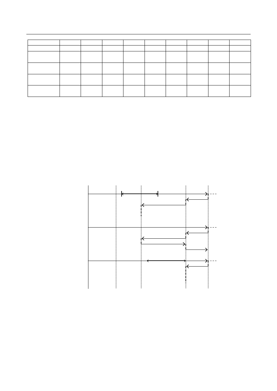
Example) 
 

Conditions of the programs of the individual paths   
Path1 ... In backward movement, there is a block that prohibits a change to forward movement.   
Path2 ... In backward movement, there is neither block that prohibits backward movement nor block 

that prohibits a change to forward movement. 

Path3 ... In backward movement, there is a block that prohibits backward movement. 

 
In the above conditions, the following operation is performed.   


STEP1:    Forward movement is performed to position A in the figure.   
STEP2, STEP3:   Backward movement is performed to position C in the figure. Path 3 is prohibited from 

moving backward at position B.   

STEP4, STEP5:   Re-forward movement is performed to position A in the figure. Since path 1 is 

prohibited from changing its direction, only path 2 performs re-forward movement. 
Even when path 2 performs re-forward movement to position B, path 3 does not start 
re-forward movement. 


STEP1 

STEP1 

STEP1 

Program 

start 

Block that prohibits a 

direction change 

STEP2 

STEP2 

STEP2 

STEP3 

STEP3 

STEP3 

STEP4 

STEP4 

STEP4 

STEP5 

STEP5 

STEP5 

Block that prohibits backward 

movement 

Path1 

Path2 

Path3 

B-64693EN-1/01


5. AUTOMATIC OPERATION


- 875 - 

To keep synchronization in re-forward movement, perform backward movement of path 1 until path 1 
passes by block D, which prohibits a direction change, and start re-forward movement of path 1.   
In this case, if bit 4 (HMP) of parameter No.6400 is set to 1 (if a path is prohibited from changing its 
movement direction, the other paths cannot also change their direction), the other paths cannot change 
their direction until path 1 passes by the position D.   


STEP1’:  Forward movement is performed to position A in the figure. 
STEP2’,STEP3’: Backward movement is performed to position D in the figure. Path 3 is prohibited from 

moving backward at position B.   

STEP4’,STEP5:  Re-forward movement is performed to position A in the figure. When path 1 and path 2 

perform re-forward movement to position B, path 3 starts re-forward movement.   


Parameter 


#7 

#6 

#5 

#4 

#3 

#2 

#1 

#0 

6400 


HMP 


[Input type]  Parameter input 


[Data type]  Bit path 


#4  HMP

  When inversion or backward movement is inhibited in other paths: 

0: 

Inversion or backward movement is not inhibited for the currently executed path. 

1: 

Inversion or backward movement is inhibited also for the currently executed path. 


#7 

#6 

#5 

#4 

#3 

#2 

#1 

#0 

18000 


RTW 


[Input type]  Parameter input 


[Data type]  Bit 


#1  RTW

  At the start of a re-forward movement operation of the manual handle retrace function in 

a multi-path system, 
0: 

The re-forward movement operation is performed immediately on each path. 

1: 

Those paths for which reverse movement are prohibited are synchronized at the stop 
position. 


STEP1’


STEP1’ 

STEP1’ 

Program 

start 

Block that prohibits a 

direction change


STEP2’ 

STEP2’ 

STEP2’ 

STEP3’ 

STEP3’ 

STEP3’ 

STEP4’ 

STEP4’ 

STEP4’ 

STEP5’ 

STEP5’ 

STEP5’ 

Block that prohibits 

backward movement


Path1 

Path2 

Path3 

5. AUTOMATIC OPERATION


B-64693EN-1/01


- 876 - 

5.3.8 

Extension of the Manual Handle Retrace Function 

Overview 

In manual handle retrace function, the following operations that were impossible so far become available.   
(1)  Forward movement of rigid tapping   
(2)  Forward movement of threading 
(3)  Forward movement of PMC axis control   
(4)  Backward movement of the orientation by the G00 command on the Cs contour control axis 
(5)  Backward movement of polygon turning with two spindles   
(6)  Backward movement of balance cutting 
This function is included in the multi-path manual handle retrace function. 
 

Explanation 

  - 

Rigid tapping 


When the bit 0 (HRA) of parameter No.6403 is set to 0 (Conventional specification) 
(1)  When rigid tapping starts during forward movement, handle operation is disabled and rigid 

tapping is executed at a speed of 100% override.   

(2)  Backward movement cannot be performed in the rigid tapping mode. In addition, when the 

rigid tapping block is reached after rigid tapping is completed in forward movement, backward 
movement cannot be done any more.   


When the bit 0 (HRA) of parameter No.6403 is set to 1 (Extensional specification) 
(1)  In tapping during forward movement, the operation is performed at a speed according to handle 

operation.   

(2)  Backward movement in rigid tapping is the same movement as in the case where bit 0 (HRA) 

of parameter No. 6403 is 0. 


  - 

Thread cutting 


When the bit 0 (HRA) of parameter No.6403 is set to 0 (Conventional specification) 
(1)  When the threading block is reached during forward movement, handle operation become 

disabled and the operation is performed at a speed of 100% override.   

(2)  Backward movement cannot be performed during threading. In addition, when the threading 

block is reached during backward movement after threading is completed in forward movement, 
backward movement cannot be done any more.   


When the bit 0 (HRA) of parameter No.6403 is set to 1 (Extensional specification) 
(1)  In threading during forward movement, the operation is performed at a speed according to 

handle operation.   

(2)  Backward movement in threading is the same movement as in the case where bit 0 (HRA) of 

parameter No. 6403 is 0.   


  WARNING 


In rigid tapping or threading during manual handle retrace, the workpiece cannot 
be actually machined.   


  - 

PMC axis control 


When the bit 1 (HRB) of parameter No.6403 is set to 0 (Conventional specification) 
(1)  The PMC axis operates independently of handle operation. 


When the bit 1 (HRB) of parameter No.6403 is set to 1 (Extensional specification) 
(1)  In PMC axis control during forward movement, the PMC axis is operated at a speed according 

to handle operation but, backward movement cannot be performed.   


B-64693EN-1/01


5. AUTOMATIC OPERATION


- 877 - 

NOTE 

1  Even when the axis specified by the program moves backward, the axis specified 

by PMC axis control cannot move backward. Therefore, the relative position 
between the axis specified by the program and the axis specified by PMC axis 
control changes when backward movement is performed while the axis that is 
specified by PMC axis control is operating. In this case, it is necessary to add the 
following PMC ladder process.   
-  When the axis specified by PMC axis control is operating, prohibit the 

backward movement of the axis specified by the program using reverse 
movement prohibition signal MRVM <Gn531.1>. 

2  Alarm PS0130 occurs when one of the following operations is executed.   

(1) In the backward movement, when PMC axis control is specified for the axis 

specified by the program in the previous block.   

(2) During PMC axis control, when a direction change is performed for the axis 

specified by the program in the previous block.   

3  In the skip (03h), continuous feed (06h), speed command (10h), torque control 

(11h), and auxiliary function (12h,13h,14h) of PMC axis control, even if bit 1 
(HRB) of parameter No. 6403 is set to 1, the axis operates independently of 
handle operation. 


  WARNING 


During the manual handle retrace, if a reset is made when a command by PMC 
axis control is not completed, the command by the program stops, but the 
command by PMC axis control continues. In this case, even if bit 1 (HRB) of 
parameter No. 6403 is set to 1, the command by PMC axis control operates 
independently of handle operation. Make a reset after confirming that the 
command by the PMC axis control is completed.   


  - 

Orientation of Cs contour control axis 


When the bit 2 (HRC) of parameter No.6403 is set to 0 (Conventional specification) 
(1)  Backward movement cannot be performed in orientation movement by the first G00 command 

after the Cs contour control mode is turned on. Therefore, when the above G00 command is 
reached during backward movement, backward movement cannot be done any more. 

(2)  Backward movement can be performed in the reference point return command (G28) of the Cs 

contour control axis, but the processing proceeds to the previous block without performing 
orientation movement.   


When the bit 2 (HRC) of parameter No.6403 is set to 1 (Extensional specification) 
(1)  Backward movement can be performed in the orientation operation by the G00 command, but 

the processing proceeds to the previous block without performing orientation movement as in 
G28 command.   

(2)  The reference point return command (G28) of the Cs contour control axis performs the same 

movement as in the case where bit 2 (HRC) of parameter No. 6403 is 0. 


  WARNING 


The workpiece cannot be actually machined because the orientation movement 
of G00 and G28 is not executed during backward movement in Cs contour 
control.   


5. AUTOMATIC OPERATION


B-64693EN-1/01


- 878 - 

  - 

Polygon machining with two spindles 


When the bit 3 (HRD) of parameter No.6403 is set to 0 (Conventional specification) 
(1)  Axes other than the polygonal synchronization axes operate at the speed according to handle 

operation even in the polygon machining mode. However, backward move cannot be 
performed in the block specified in the polygonal machining mode.   

(2)  When the  polygon machining block (G50.2) is reached in backward movement after the 

polygon machining is completed in forward movement, backward movement cannot be done 
any more.   


When the bit 3 (HRD) of parameter No.6403 is set to 1 (Extensional specification) 
(1)  It is possible to move backward or re-forward in the block specified in the polygonal machining 

mode. When backward movement is performed during polygon machining, however, if the 
polygon machining-on block (G51.2) is reached, backward movement cannot be done  any 
more. 

(2)  The operation when the polygon machining block (G50.2) is reached in backward movement 

after the polygon machining is completed in forward movement the same as in the case where 
bit 3 (HRD) of parameter No. 6403 is 0.   


  WARNING 

In the threading and polygon machining between two spindles, the spindle 
operates at a speed of override 100% instead of the speed according to handle 
operation. Therefore, the workpiece cannot be actually machined.   
 
(Example) Treading during the manual handle retrace 


Tool (Handle operation)


Workpiece (Spindle override 100%)


The threads may be incorrectly cut in manual 

handle operation


Workpiece (spindle override 100%)


  - 

Balanced cutting 


When the bit 4 (HRE) of parameter No.6403 is set to 0 (Conventional specification) 
(1)  In the balance cutting mode, axes operate at the speed according to handle operation, but 

backward movement cannot be performed.   

(2)  When the balance cutting block (G69) is reached in backward movement after the balance 

cutting is completed in forward movement, backward movement cannot be done any more.   


When the bit 4 (HRE) of parameter No.6403 is set to 1 (Extensional specification) 
(1)  It is possible to move backward or re-forward in the block specified in the balance cutting 

mode. When backward movement is performed in the balance cutting mode, if the balance 
cut-on block (G68) is reached, backward movement cannot be done any more.   

(2)  The operation when the balance cutting block (G69) is reached in the backward movement after 

the balance cutting was  completed in forward movement is the same operation as in the case 
where bit 4 (HRE) of parameter No. 6403 is 0.   


B-64693EN-1/01


5. AUTOMATIC OPERATION


- 879 - 

NOTE 

1  In the balance cutting mode, waiting is done so that the block starts at the same 

time in each path. Backward movement cannot start during the waiting. After the 
waiting is completed and the next block starts, backward movement becomes 
possible.   


Path 1:  Backward movement is disabled 

because waiting is under way. 

Path 2:  Backward movement is 

enabled. 

Path 2: Backward movement is enabled. 

Path 1: Backward movement is enabled. 

After waiting is completed 


2  In all paths that uses balance cutting, set bit 4 (HRE) of parameter No. 6403 to 1. 


Parameter 


#7 

#6 

#5 

#4 

#3 

#2 

#1 

#0 

6403 


HRE 

HRD 

HRC 

HRB 

HRA 


[Input type]  Parameter input 


[Data type]  Bit path 


#0  HRA

  In rigid tapping and thread cutting, with the manual handle retrace function, program 

execution in the forward direction: 
0: 

Cannot be performed. 

1: 

Can be performed. 


#1  HRB

  In PMC axis control, with the manual handle retrace, program execution in the forward 

direction: 
0: 

Cannot be performed. 

1: 

Can be performed. 


#2  HRC

  During orientation operation according to G00 for a Cs contour control axis, with the 

manual handle retrace function, program execution in the backward direction: 
0: 

Cannot be performed. 

1: 

Can be performed. 


#3  HRD

  In polygon machining with two spindles, with the manual handle retrace function, 

program execution in the backward direction: 
0: 

Cannot be performed. 

1: 

Can be performed. 


#4  HRE

  In balanced cutting, with the manual handle retrace function, program execution in the 

backward direction: 
0: 

Cannot be performed. 

1: 

Can be performed. 

5. AUTOMATIC OPERATION


B-64693EN-1/01


- 880 - 

5.4 

MANUAL ABSOLUTE ON/OFF 

Overview 

Whether the distance by which the tool is moved by manual operation (such as jog feed or manual handle 
feed) is reflected in the absolute coordinate system can be selected. 
 

  - 

When manual absolute turns on 

When manual intervention is performed during automatic operation, the distance by which the tool is 
moved by manual intervention is reflected in the absolute coordinate system. For this reason, the absolute 
and machine coordinate systems are the same before and after manual intervention. 
The tool path after manual intervention is determined according to the setting of bit 1 (ABS) of parameter 
No. 7001 as follows. 


For an absolute command, or incremental command with bit 1 (ABS) 
of parameter No. 7001 set to 1, the path indicates the program path. 

Manual 
interruption 

Program path 

For an incremental command with bit 1 (ABS) of parameter No. 7001 set to 
0, the path is shifted. 


Fig. 5.4 (a) 


  - 

When manual absolute turns off 

The distance by which the tool is moved is reflected in the absolute position display during manual 
operation. 
When the system is reset or restarted in the automatic operation mode after manual operation, however, 
the absolute position display indicates the position before manual intervention and the absolute coordinate 
system after manual intervention is shifted from the machine coordinate system by the amount of manual 
intervention. The tool path after manual intervention is as follows. 


Manual 
interruption 

Program path 

The path is shifted regardless of an absolute or incremental command. 


Fig. 5.4 (b) 


Signal 

Manual absolute signal *ABSM<Gn006.2> 

    [Classification]  Input signal 
 

  [Function]  Turns the manual absolute function on or off. 


  [Operation]  When this signal is set to 0, turns on the manual absolute function. 

When this signal is set to 1, turns off the manual absolute function. 


B-64693EN-1/01


5. AUTOMATIC OPERATION


- 881 - 

Manual absolute check signal MABSM<Fn004.2> 

  [Classification]  Output signal 
 

[Function]  Notifies the state of the manual absolute signal. 

    [Output cond.]  This signal is set to 1 in the following case: 

When the manual absolute signal *ABSM is set to 0 

This signal is set to 0 in the following case: 

When manual absolute signal *ABSM is set to 1 


Signal address 


#7 

#6 

#5 

#4 

#3 

#2 

#1 

#0 

Gn006 


*ABSM 


Fn004 


MABSM 


Parameter 


#7 

#6 

#5 

#4 

#3 

#2 

#1 

#0 

7001 


ABS 


[Input type]  Parameter input 


[Data type]  Bit path 


#1  ABS

  For the move command after manual intervention in the manual absolute on state: 

0: 

Different paths are used in the absolute (G90) and incremental (G91) modes. 

1: 

The same path (path in the absolute mode) is used in the absolute (G90) and 
incremental (G91) modes. 


Reference item 

Manual name 

Item name 

OPERATOR’S MANUAL (B-64694EN) 

Manual absolute on/off 


5.5 

OPTIONAL BLOCK SKIP/ADDITION OF OPTIONAL 
BLOCK SKIP 

Overview 

When a slash followed by a number (/n, where n = 1 to 9) is specified at the head of a block, and optional 
block skip signals BDT1 to BDT9 are set to 1 during automatic operation, the information contained in 
the block for which /n, corresponding to signal BDTn, is specified is ignored (from /n to the end of the 
block). 
(Example) 
 

/2 N123 X100.0 Y200.0 ; 

Table 5.5 (a) 

Input signal 

Code specified at the head of a block 

BDT1 
BDT2 
BDT3 
BDT4 
BDT5 
BDT6 
BDT7 
BDT8 
BDT9 

/ or /1 

(Note)


/2 
/3 
/4 
/5 
/6 
/7 
/8 
/9 


Content      ..     113      114      115      116     ..