FANUC Series 0i-MODEL F Plus. CONNECTION MANUAL (FUNCTION) - page 116
 

  Index      Manuals     FANUC Series 0i-MODEL F Plus. CONNECTION MANUAL (FUNCTION) B-64693EN-1/01


Search            copyright infringement  


Content      ..     114      115      116      117     ..


FANUC Series 0i-MODEL F Plus. CONNECTION MANUAL (FUNCTION) - page 116


5. AUTOMATIC OPERATION


B-64693EN-1/01


- 882 - 

NOTE 


Number 1 for /1 can be omitted. However, when two or more optional block skip 
switches are used in one block, number 1 for /1 cannot be omitted. 

 
(Example) 

//3 N123 X100.0 Y200.0 ; Invalid 
/1 /3 N123 X100.0 Y200.0 ; Valid 


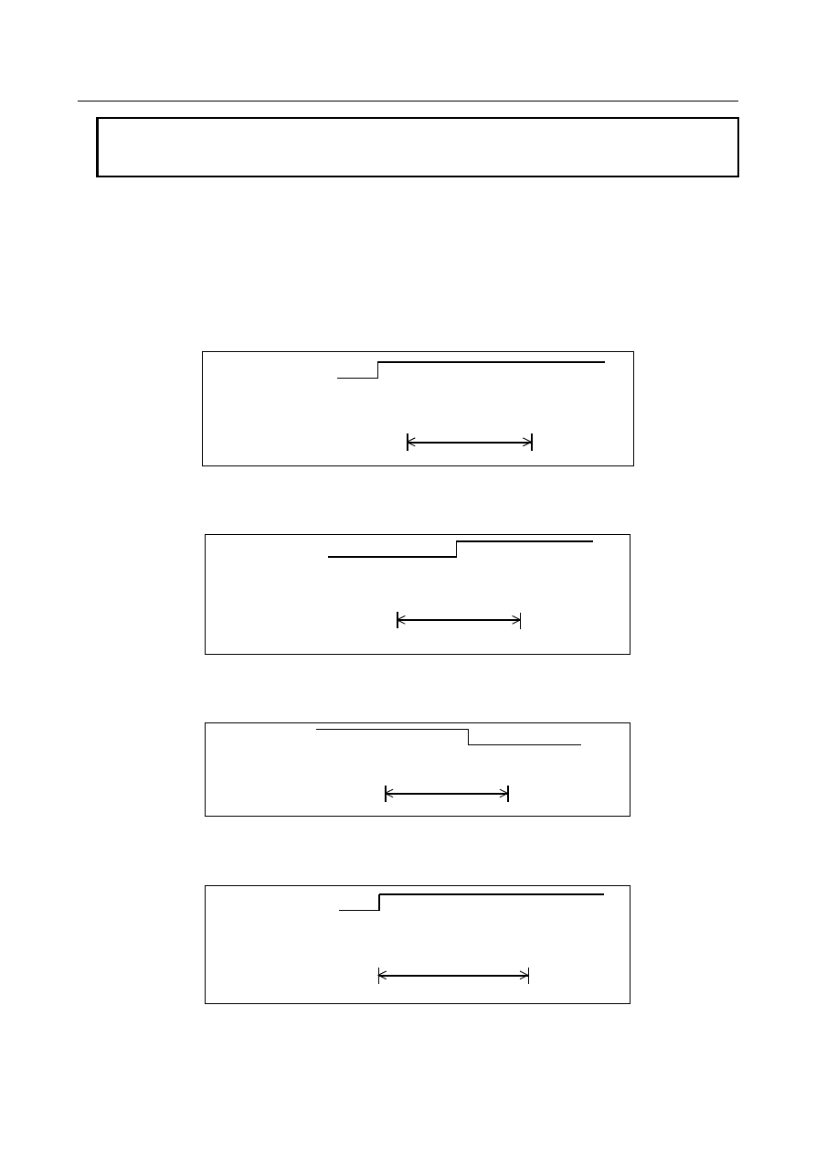
The following figures show the relationship between the timing, when optional block skip signals 
(BDT1 to BDT9) are set to 1, and the ignored information: 


1. 

When BDTn is set to  1 before the CNC starts reading a block containing /n, the block is 
ignored. 


BDTn 

"1" 


"0" 


Reading by CNC 

 . . .    ; /n N123 X100. Y200. ; N234 . . .   


Ignored 


Fig. 5.5 (a) 

 
2. 

When BDTn is set to 1 while the CNC is reading  a block containing /n, the block is not 
ignored. 


BDTn  "1" 
 

"0" 


Reading by CNC 

 . . .    ; /n N123 X100. Y200. ; N234 . . . . 


Not ignored 


Fig. 5.5 (b) 

 
3. 

When BDTn, currently set to 1, is set to 0 while the CNC is reading a block containing /n, the 
block is ignored. 


BDTn  "1" 
 

"0" 


Reading by CNC 

 . . .    ; /n N123 X100. Y200.;    N234 . . . . 


Ignored 


Fig. 5.5 (c) 

 
4. 

Two or more optional block skip switches can be specified in a block and the block is ignored 
when BDTn corresponding to one of them is set to 1. 


BDT3  "1" 
 

"0" 


Reading by CNC 

 . . .    ; /1 /3 /5 N123 X100. Y200. ;    N234 . . . 

Ignored 


Fig. 5.5 (d) 


B-64693EN-1/01


5. AUTOMATIC OPERATION


- 883 - 

Note 

NOTE 

1  This function is ignored when programs are loaded into memory. Blocks 

containing /n are also stored in memory, regardless of how the optional block skip 
signal is set. 


Programs stored in memory can be output, regardless of how the optional block 
skip signals are set. 


Optional block skip is effective even during sequence number search operation. 

2  Position of a slash 

A slash (/) must be specified at the head of a block. If a slash is placed 
elsewhere, the information from the slash to immediately before the EOB code is 
ignored. 

3  TV and TH check 

When an optional block skip signal is 1. TH and TV checks are made for the 
skipped portions in the same way as when the optional block skip switch is 0. 

4  When bit 6 (BDA) of parameter No.11504 is 0 and the optional block skip is 

invalid and /2 to /9 is specified, the specifying of optional block skip is ignored and 
the block is executed. When bit 6 (BDA) of parameter No.11504 is 1 and the 
optional block skip is invalid and /2 to /9 is specified, the alarm PS0004 "INVALID 
BREAK POINT OF WORDS" is generated. 


Signal 

Optional block skip signals BDT1<Gn044.0>, BDT2 to BDT9<Gn045> 

  [Classification]  Input signal 
 

[Function]  Select whether a block containing /n is to be executed or ignored. 


[Operation]  During automatic operation, a block containing /n in the program is ignored when the 

corresponding optional block skip signal is set to 1. It is executed normally when the 
signal is set to 0. 


Optional block skip check signals MBDT1<Fn004.0>, MBDT2 to MBDT9<Fn005> 

  [Classification]  Output signal 
 

[Function]  Notify the PMC of the states of the optional block skip signals BDT1 to BDT9. Nine 

signals are provided, corresponding to the nine  optional block skip signals. Signal 
MBDTn corresponds to signal BDTn. 


[Output cond.]  Signal MBDTn is set to 1 in the following case: 

When the corresponding optional block skip signal (BDTn) is set to 1 

Signal MBDTn is set to 0 in the following case: 

When the corresponding optional block skip signal (BDTn) is set to 0 


Signal address 


#7 

#6 

#5 

#4 

#3 

#2 

#1 

#0 

Gn044 


BDT1 


Gn045 


BDT9 

BDT8 

BDT7 

BDT6 

BDT5 

BDT4 

BDT3 

BDT2 


#7 

#6 

#5 

#4 

#3 

#2 

#1 

#0 

Fn004 


MBDT1 


Fn005 


MBDT9 

MBDT8 

MBDT7 

MBDT6 

MBDT5 

MBDT4 

MBDT3 

MBDT2 


5. AUTOMATIC OPERATION


B-64693EN-1/01


- 884 - 

Parameter 

Parameters which are used for this function are as follows. 


#7 

#6 

#5 

#4 

#3 

#2 

#1 

#0 

11504 


BDA 


  [Input type]  Parameter input 


  [Data type]  Bit


#6  BDA

  When the optional block skip is disabled and /2 to /9 is specified: 

0: 

Alarm is not generated. 

1: 

Alarm PS0004 "INVALID BREAK POINT OF WORDS" is generated. 


NOTE 

1  This parameter is disabled to sequence number search operation. 
2  This parameter is disabled to macro executor (conversational 

macro, auxiliary macro). 


Reference item 

Manual name 

Item name 

OPERATOR’S MANUAL (B-64694EN) 

Optional block skip/addition optional block skip   


5.6 

PROGRAM RESTART 

Overview 

When the tool is broken during automatic operation, or when a machining operation interrupted by a 
holiday is to be restarted after the holiday, you can restart machining from a desired block by specifying 
the sequence number of the block or the number of blocks from the beginning of the program to the block 
where machining is to restart. 
This function can also be used as a high-speed program check function. 
There are two types of restarting methods as follows. 
P type: 

Restart after a tool is broken down 

Q type: 

Restart after the power is turned off (after a holiday, etc.) or after emergency stop is canceled 


Explanation 

  - 

Outputting M, S, T, and B (second auxiliary function) codes on the program 
restart screen


By setting bit 7 (MOU) of parameter No. 7300, the M, S, T, and B (second auxiliary function) codes can 
be output after a block where the program is to restart is searched for. 

Before a movement to the machining restart point 
<1>  The last M, S, T, and B (2nd auxiliary function) codes can be output to the PMC automatically. 

The last S code is output as the maximum spindle speed if the S code is specified together with 
G92 in one block; otherwise, the S code is output as a specified spindle speed. On the program 
restart screen, only the S code specified last is indicated regardless of whether it is specified 
together with G92 in one block or not. 

<2>  All M codes sampled during the search for the block where the program is to restart and the last 

S, T, and B (second auxiliary function) codes can be output to the PMC automatically. 
Up to 35 M cods can be sampled. If there are more than 35 M codes to be sampled, the latest 35 
M codes are output to the PMC. 


<1> or <2> above can be selected by setting bit 6 (MOA) of parameter No. 7300. 


B-64693EN-1/01


5. AUTOMATIC OPERATION


- 885 - 

2


Until the machining restart point is reached (over store mode) 
On the program restart screen, you can specify M, S, T, and B (second auxiliary function) codes 
through MDI key input while maintaining the MEM mode or DNC mode. 


Movement to the restart point


No.7310 sets the ordinal number of an axis along which a movement is made in dry run after program 
restart. When No.7310 is not set, alarm SR5020 “PARAMETER OF RESTART ERROR” or the warning 
“ORDINAL NUMBER ERROR (RESTART)” is displayed. 
 

Presetting the relative coordinate values after the search


If  bit  3  (RPR) of parameter No.7301 is 1, relative coordinate  values are preset by absolute coordinate 
values after the search in program restart. 
 

Limitation 

  - 

P type Restart 

In the following conditions, P type restart cannot be performed: 

Bit 7 (SQP) of parameter No. 13117 is set to 1. 

Automatic operation has not been performed since power-on. 

Automatic operation has not been performed since emergency stop was released. 

Automatic operation has not been performed since the coordinate system was changed or shifted 
(change of the external workpiece origin offset value).   

The block that can be restored properly by P type program restart is a block for which coordinate system 
setup or change was performed most recently before machining was interrupted. 
 

Block number specification Restart 

In the following conditions, the block number specification restart cannot be performed: 

Bit 6 (SQB) of parameter No. 13117 is set to 1. 

Specified block number could not be found. (Alarm PS0071 “DATA NOT FOUND” occurs. 


  - 

Restart block 

The block where the program  is to restart is not necessarily be the block at which the program was 
interrupted. You can restart the program from any block. For P-type restart, however, the block where the 
program is to restart must use the same coordinate system as when program execution was interrupted. 
 

  - 

Single block 

When the single-block operation is enabled at the time of a movement to the restart point, a single-block 
stop occurs each time an axis operation takes place. In this case, no MDI operation is allowed. 
 

  - 

Manual intervention 

During movement to the restart point, manual intervention is allowed for an axis for which a return 
operation has not yet been performed. However, manual operations do not cause any movement along 
axes for which a return operation has already been completed. 
 

  - 

MDI 

When the search operation has ended, no move command can be specified by MDI before axis 
movement. 
 

  - 

Reset 

Do not perform a reset operation during the time from the start of the search operation of the restart 
sequence until machining is restarted. 
If a reset operation is performed, the restart steps must be performed again from the beginning. 
 

5. AUTOMATIC OPERATION


B-64693EN-1/01


- 886 - 

  - 

Feed hold 

If a feed hold operation is performed during the search, the restart steps must be performed again from the 
beginning. 
 

  - 

Manual absolute 

Every manual operation must be performed with the manual absolute mode turned on regardless of 
whether the manual operation is performed before or after machining. 
 

  - 

Reference position return 

Unless an absolute position detector (absolute pulse  coder) is provided, be sure to perform reference 
position return after power-up, then perform restart operation. 
 

  - 

Program restart signal 

When program restart signal SRN <Gn006.0> is set to "1", pressing the cycle start does not cause a start. 
 

  - 

Blocks specifying a macro statement, macro call, and subprogram call 

Blocks specifying a macro statement, macro call, and subprogram call are not searched for even when 
they have a sequence number. In such a case, search for a block previously preceding such a block. 
 

  - 

Interruption type custom macro 

During movement to the machining restart point at a dry run feedrate, no interruption type custom macro 
can be started. If an interruption type custom macro is started, alarm DS0024 is issued. 
 

  - 

Commands that prevent program restart 

Program restart cannot be performed for blocks placed in the following modes: 

Polar coordinate interpolation (G12.1) 

Threading (G32,  G33), Circular threading (G35,  G36), Threading cycle (G92), Multiple repetitive 
threading cycle (G76) 

Polygon turning (G50.2) 

Balance cutting (G68) 

Rigid tapping 

Spindle positioning 

If any of the following commands is included between the beginning of a program and the block where 
the program is to restart, program restart cannot be performed: 

Workpiece coordinate system preset (G92.1, G50.3) 

Commands for enabling and disabling synchronous/mixture control and superimposed control   

Commands for enabling and disabling axis synchronous control 


  - 

M, S, and T commands not usable in over store mode 

The M, S, and T functions listed below, unlike the other M, S, and T functions, have special meanings 
within the CNC. These M, S, and T commands cannot be specified from the over store screen. To specify 
these commands, cancel the over store mode, and execute them in MDI operation. 
Example: 

Spindle positioning 

Rigid tapping 

Tool management 

Tool offset for lathe system (T code) 


  - 

Tool radius / Tool nose radius compensation 

When bit 4 (INT) of parameter No. 13117 is set to 1, the interference check on Tool radius/tool nose 
radius compensation can be disabled during search. 
 

B-64693EN-1/01


5. AUTOMATIC OPERATION


- 887 - 

  - 

Cs contour control 

Usually, before a program restart operation can be started, it is necessary to enter Cs contour control 
mode and establish the origin of the Cs contour controlled axis. 
By using the Cs axis coordinate establishment function and setting bit 5 (CCS) of parameter No. 7300 to 
1, however, it is no longer necessary to enter Cs contour control mode or establish the origin of the Cs 
contour controlled axis before starting a program restart operation. 
In this case, it is possible to change to Cs contour control mode, if necessary, after the end of the search 
for the block subject to the restart. 
If the system enters Cs contour control mode, the origin of the Cs contour controlled axis is established 
with the Cs axis coordinate establishment function. And, the "DISTANCE TO GO" of the Cs contour 
controlled axis is recalculated. 
 

NOTE 


To use Cs contour control axis coordinate establishment, perform reference 
position return for the Cs contour control axis at least once after power on. 
For details, refer to “Cs Contour Control Axis Coordinate Establishment” in this 
manual. 


  - 

Flexible synchronization control 

Setting bit 0 (FRS) of parameter No. 13421 to 1 enables program restart in a program containing an M 
code for turning the flexible synchronization mode on or off. 
1. 

Before starting program restart, set the flexible synchronization control mode selection signal MTA 
<Gn197.0>, MTB <Gn197.1>, MTC <Gn197.2>, or MTD <Gn197.3> to set the synchronization 
mode specified in the program command in the block where the program is to restart (the state 
specified by an M code for turning the flexible synchronization mode on or off).   


If the signal setting is inconsistent with the state specified by the M code, alarm PS5374 occurs. The 
synchronization mode is assumed to be off in the program from the beginning of the program until 
the first M code for turning the flexible synchronization mode on or off is specified. 

2. 

The flexible synchronization mode cannot be changed during the execution of program restart (when 
signal SRNMV <Fn002.4> is set to "1"). If an attempt is made to change the mode, alarm PS5375 
occurs. 

3. 

When a block in the flexible synchronization mode is specified as the restart block, 0 is displayed for 
DISTANCE TO GO for the slave axis. In addition, “********” is displayed as the restart position 
for the slave axis. 

4. 

To restart a program from a block after the flexible synchronization mode is canceled, an absolute 
command must be specified for the slave axis after the mode is canceled. If no absolute command is 
specified for the slave axis, alarm PS5378 occurs. 


  - 

3-dimensional coordinate system conversion / Tilted working plane command 

When the block where the program is to restart is in 3-dimensional coordinate system conversion mode 
G68 (machining center system) or G68.1 (lathe system) or Tilted working plane command, bit 1 (3DD) of 
parameter No. 7301 can be set to select whether to move the tool to the restart position along each axis 
according to the program coordinate system or workpiece coordinate system. When the bit (3DD) is set to 
0, the tool moves to the restart position along each axis according to the program coordinate system; 
when it is set to 1, the tool moves according to the workpiece coordinate system. 
The “DESTINATION” and “DISTANCE TO GO” values are displayed according to the setting of this bit 
(3DD). 
The "ABSOLUTE" values are displayed according to the setting of bit 6 (DAK) of parameter No. 3106. 
 

  - 

Setting to prevent movement to restart position   

When there are two or more axes which has the same setting value in parameter No.7310, the movement 
to the restart position is not executed in the second or more axis. 
 

5. AUTOMATIC OPERATION


B-64693EN-1/01


- 888 - 

Signal 

Program restart signal SRN<Gn006.0> 

    [Classification]  Input signal 
 

  [Function]  Selects program restart. 


[Operation]  When the program restart signal is set to "1"  to search for the sequence number of the 

block to be restarted, the screen changes to the program restart screen. When the program 
restart signal is set to "0", and automatic operation is activated, the tool is moved back to 
the machining restart point at dry run speed along the axes one by one in the sequence 
specified in parameter No. 7310. When the tool is set to the restart point, machining 
restarts. 


Program restart under way signal SRNMV<Fn002.4> 

    [Classification]  Output signal 
   

[Function]  Indicates the program is being restarted. 

    [Output cond.]  The program restart under way signal becomes "1" when: 

The program restart signal is set to "0"  after the screen changes to the program 
restart screen. 

The signal is set to "0" when: 

The program restart sequence ends (the tool has been moved to the restart point on 
all controlled axes). 


Signal address 


#7 

#6 

#5 

#4 

#3 

#2 

#1 

#0 

Gn006 


SRN 


Fn002 


SRNMV 


Parameter 


#7 

#6 

#5 

#4 

#3 

#2 

#1 

#0 

7300 


MOU 

MOA 

CCS 


[Input type]  Parameter input 


[Data type]  Bit path 


#5  CCS

  When the Cs contour control axis is used in the spindle mode or when the origin of the Cs 

contour control axis is not established, program restart is: 

0: 

Disabled.


1: 

Enabled. 


#6  MOA

  In program restart operation, before movement to a machining restart point: 

0: 

The last M, S, T, and B codes are output. 

1: 

All M codes and the last S, T, and B codes are output. 

This parameter is enabled when the bit 7 (MOU) of parameter No.7300 is set to 1. 


#7  MOU

  In program restart operation, before movement to a machining restart point after restart 

block search: 
0: 

The M, S, T, and B codes are not output. 

1: 

The last M, S, T, and B codes are output. 


#7 

#6 

#5 

#4 

#3 

#2 

#1 

#0 

7301 


RPR 


3DD 

ROF 


[Input type]  Parameter input 


[Data type]  Bit path 

B-64693EN-1/01


5. AUTOMATIC OPERATION


- 889 - 


#0    ROF

  When the coordinates for restarting are displayed on the program restart screen: 

0: 

Tool length compensation (M series), tool position compensation (T series), cutter 
compensation (M series), and tool-nose radius compensation (T series) are 
considered. 

1: 

Whether these compensation values are considered depends on the settings of bit 6 
(DAL) of parameter No. 3104, bit 7 (DAC) of parameter No. 3104, and bit 1 (DAP) 
of parameter No. 3129 (parameters for specifying whether to consider each 
compensation value). 


#1  3DD

  In program restart operation, when the restart block is in 3-dimensional coordinate 

conversion mode G68 (machining center system) or G68.1 (lathe system), the tool moves 
to the restart point along each axis: 
0: 

According to the program coordinate system in dry run. 

1: 

According to the workpiece coordinate system in dry run. 

The restart coordinates and restart travel distance are also displayed in the coordinate 
system set in this parameter. 
 

NOTE 

The change made to this parameter in program restart operation is 
ignored. 


#3  RPR

  When the search is completed in program restart or quick program restart, relative 

coordinate values are: 
0: 

Not preset. 

1: 

Preset by absolute coordinate values. 


NOTE 

This parameter is invalid in direct jump method of quick program 
restart. 


7310 


Ordinal number of an axis along which a movement is made in dry run after program restart 


[Input type]  Setting input 


[Data type]  Byte axis 

[Valid data range]  1 to (Number of controlled axes) 

This parameter sets the ordinal number of an axis along which a movement is made in dry 
run after the program is restarted. 
 

  WARNING 

1  When there is two or more axes which has the same setting value in 

this parameter, the movement to the restart point is not executed in 
the second or more axis. 

2  When the quick program restart is effective and bit 6 (SAV) of 

parameter No.11250 is set to 1, the movement to the restart point is 
not done in the axis which this parameter is set negative value(-1 to 
-(Number of controlled axes)). 


NOTE 


When this parameter is 0, alarm SR5020, "PARAMETER OF 
RESTART ERROR" or the warning "ORDINAL NUMBER ERROR 
(RESTART)" is displayed. 


Content      ..     114      115      116      117     ..