FANUC Series 0i-MODEL F Plus. CONNECTION MANUAL (FUNCTION) - page 103
 

  Index      Manuals     FANUC Series 0i-MODEL F Plus. CONNECTION MANUAL (FUNCTION) B-64693EN-1/01


Search            copyright infringement  


Content      ..     101      102      103      104     ..


FANUC Series 0i-MODEL F Plus. CONNECTION MANUAL (FUNCTION) - page 103


4. REFERENCE POSITION ESTABLISHMENT


B-64693EN-1/01


- 778 - 

 
The automatic setting procedure is as follows: 
<1>  Set an appropriate value in parameters Nos. 1815, 1821, and 1882. 

(In case of the linear scale with distance-coded reference marks (serial), it is not 
necessary to set the parameter No.1882.) 

<2>  Position the machine at the reference position by manual operation. 
<3>  Set this parameter to 1. 

Alarm PS5220, “REFERENCE POINT ADJUSTMENT MODE”, occurs. 

<4>  Perform a manual reference  position  return  operation. Upon completion  of manual 

reference position return operation, parameters Nos. 1883 and 1884 are set, and this 
parameter is automatically set to 0. 
Make a reset to release alarm PS5220. 


1883 


Distance 1 from the base point to reference position 


NOTE 


When this parameter is set, the power must be turned off before 
operation is continued. 


[Input type]  Parameter input 


[Data type]  2-word axis 


[Unit of data]  Detection unit 

[Valid data range]  -999999999 to 999999999 


1884 


Distance 2 from the base point to reference position 


NOTE 


When this parameter is set, the power must be turned off before 
operation is continued. 


[Input type]  Parameter input 


[Data type]  2-word axis 


[Unit of data]  Detection unit 

[Valid data range]  -999 to 999 

Set the distance from the base point to the reference position in parameter Nos. 1883 and 
1884. The base point is a point at a scale end as shown Fig. 4.9 (a). 


Mark 1


Mark 2 

Mark 1


Mark 2 

Mark 1


Mark 1


Mark 2


Reference position 


10.020 

9.980 

10.040 

9.960 

10.060 

9.940 

Base point 

20.000 

20.020 


Fig. 4.9 (a) 

 
If the reference position is located in the positive direction when viewed from the base 
point, set a positive value; if the reference position is located in the negative direction, set 
a negative value. Set the value by following the steps explained below. 

B-64693EN-1/01


4. REFERENCE POSITION ESTABLISHMENT


- 779 - 

<1>  Set bit 1 (OPT) of parameter No. 1815 , bit 2 (DCL) of parameter No. 1815, and bit 

3 (SDC) of parameter No. 1818 to enable this function. 
Set 0 in parameter No. 1240. 
Set 0 in parameter Nos. 1883 and 1884. 

<2>  At an appropriate position, establish a reference position. 

(Consequently, the machine coordinate value indicates the distance from the base 
point to current position.) 

<3>  By jog feed or handle feed, place the machine at the accurate reference position. 
<4>  In parameters Nos. 1883 and 1884, set the machine coordinate of that time converted 

to the detection unit (machine coordinate 

×

 CMR). 

If necessary, set parameter No. 1240. 
 

NOTE 

1  Set parameter Nos. 1883 and 1884 so that the distance from the 

base point to the reference position is within the range from 
-999,999,999,999 to +999,999,999,999. If a value beyond this 
range is set, an alarm DS0016, "SERIAL DCL:FOLLOW-UP 
ERROR", is issued. 

2  The scale area on the scale cannot be extended across the base 

point. Make parameter settings not to cause the scale area to 
extend beyond the base point. 


14010 


Maximum allowable travel distance when the reference position is established for a linear scale with an 

absolute address reference position 


[Input type]  Parameter input 


[Data type]  2-word axis 


[Unit of data]  Detection unit 

[Valid data range]  0 to 99999999 

This parameter sets the maximum allowable travel distance at the FL rate when the 
reference position is established for a linear scale with an absolute address reference 
position. When the travel distance exceeds the setting of this parameter, the alarm 
DS0017, “SERIAL DCL:REF-POS ESTABLISH ERR” is issued. When this parameter is 
set to 0, the maximum allowable travel distance is not checked. 
 

NOTE 

1  To establish the reference position with axis synchronous control, 

set the parameter for both master and slave axes. 

2  In angular axis control, the setting of this parameter is invalid to the 

orthogonal axis where the reference position on the angular axis is 
being established. 


Alarm and message 

No. 

Message 

Description 

PS0372 

REFERENCE RETURN 
INCOMPLETE 

An attempt was made to perform an automatic return to the 
reference position on the orthogonal axis before the completion of a 
return to the reference position on the angular axis. 
However, this attempt failed because a manual return to the 
reference position during angular axis control or an automatic return 
to the reference position after power-up was not commanded. First, 
return to the reference position on the angular axis, then return to 
the reference position on the orthogonal axis. 

4. REFERENCE POSITION ESTABLISHMENT


B-64693EN-1/01


- 780 - 

No. 

Message 

Description 

PS0376 

SERIAL DCL: ILLEGAL 
PARAMETER 

1.  When bit 1 (OPTx) of parameter No. 1815 is set to 1, bit 3 

(PFSE) of parameter No. 2002 is set to 0 

2.  The absolute-position detection function is enabled. (Bit 5 

(APCx) of parameter No. 1815 is set to 1.) 

PS5220 

REFERENCE POINT 
ADJUSTMENT MODE 

In case of distance coded linear scale I/F, the reference point auto 
setting bit 2 (DATx) of parameter No. 1819 is set to 1. Move the 
machine to reference position by manual operation and execute 
manual reference return. 

DS0016 

SERIAL DCL:FOLLOW-UP 
ERROR 

1.  The specification of parameter No. 1883 or 1884 is out of range. 
2.  During the establishment of an origin, the distance between the 

current position and the reference position (detection unit) 
exceeded 

±

2147483647. To avoid this situation, modify either 

the current position or the reference position. 

DS0017 

SERIAL DCL:REF-POS 
ESTABLISH ERR 

During the establishment of an origin, the amount of travel at the FL 
feedrate exceeded the setting of parameter No. 14010. 

DS0018 

SERIAL DCL:MISMATCH 
(SSYNC CTRL) 

Master/slave axes of axis synchronous control, one of them is the 
linear scale with distance-coded reference marks (serial) and the 
other of them is not the linear scale with distance-coded reference 
marks (serial). Please establish reference position with the input 
signal SYNCn<G138>, SYNCJn<G140> or bit 5 (SCA) of parameter 
No. 8304 setting to 0. 

DS0019 

SERIAL 
DCL:MISMATCH(ANGL-AXIS) 

On angular axis control, one of the angular/perpendicular axes is the 
scale with ref-pos, and the other of them is not the scale with 
ref-pos. Such system is not admired. 

DS0020 

REFERENCE RETURN 
INCOMPLETE 

An attempt was made to perform an automatic return to the 
reference position on the orthogonal axis before the completion of a 
return to the reference position on the angular axis. 
However, this attempt failed because a manual return to the 
reference position during angular axis control or an automatic return 
to the reference position after power-up was not commanded. First, 
return to the reference position on the angular axis, then return to 
the reference position on the orthogonal axis. 

SV0366 

PULSE MISS(INT) 

A pulse error occurred on the built-in Pulsecoder. 

SV0367 

COUNT MISS(INT) 

A count error occurred on the built-in Pulsecoder. 

SV0382 

COUNT MISS(EXT) 

A count error occurred on the separate detector. 

SV0383 

PULSE MISS(EXT) 

A pulse error occurred on the separate detector. 


Caution 


  CAUTION 

1  When the Linear scale with distance-coded reference marks (serial) is used, set 

bit 3 (SDCx) of parameter No. 1818 of the corresponding axis to 1. 

B-64693EN-1/01


4. REFERENCE POSITION ESTABLISHMENT


- 781 - 

  CAUTION 

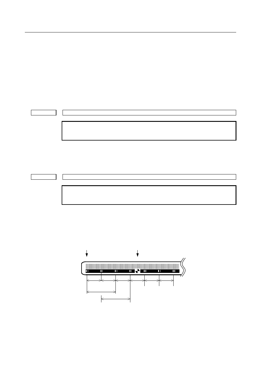
2  On the Linear scale with distance-coded reference marks (serial), the axis does 

not stop until three reference marks are detected. If this procedure is started at 
the position near the scale end, CNC can not detect three reference marks and 
the axis does not stop until over travel alarm occurs. Please care to start at the 
position that has enough distance from scale end. 


And if establishment of reference position is failed, the establishment is retried. 
Then axis does not stop until still more three reference marks are detected. So 
set the maximum move amount (detection unit: parameter No.14010) not to 
reach the scale end. 


Scale end


Reference marks


Start point (Bad) 

Start point (Good) 


3  On flexible synchronization mode, reference position can't be established. 
4  In case that straightness compensation function is used, the movement is 

explained below. 


When the reference position establishment of moving axis is executed after the 
establishment of compensation axis after power on, the compensation axis is 
moved by straightness compensation amount when the reference point of 
moving axis is established. 

5  It is not available to use this function and the temporary absolute coordinate 

setting together. 

6  This function cannot be used together with synchronous control, composite 

control, and superimposed control. 

7  When the axis used this function, the following function can not be used. 

- Absolute position detection 


4.10 

EXTENDED FUNCTION OF THE DISTANCE CODED 
LINEAR SCALE INTERFACE 

Overview 

The distance coded linear scale interface has reference marks at intervals that change at a constant rate. 
By determining the reference mark interval, the corresponding absolute position can be deduced. When a 
G00 command or a move command in jog feed is specified for an axis for which the distance coded linear 
scale interface is used, this function establishes the reference position by measuring the reference mark 
intervals automatically. Therefore, after CNC power-up, the reference position can be established without 
performing reference position return operation. 


Reference 
mark 1 

Reference 
mark 2 

Reference 
mark 1 

Reference 
mark 2 

Reference 
mark 1 

10.02 

10.04 

20.02 

20.00 

20.00 

10.06 


Fig. 4.10 (a) Sample distance coded linear scale interface 

4. REFERENCE POSITION ESTABLISHMENT


B-64693EN-1/01


- 782 - 

To use this function, the distance coded linear scale interface is also required. 
 

4.10.1 

Reference Position Established by the G00 Command 

Explanation 

  - 

Activation conditions 

When the following conditions are satisfied, reference position establishment operation is performed 
automatically: 
<1>  A G00 command is specified to cause a movement along an axis for which no reference position has 

been established. 

<2>  The movement direction in <1> above matches the reference position return direction set by bit 5 

(ZMI) of parameter No. 1006. 

<3>  The specified axis is not in the following modes: 


3-dimensional coordinate conversion 


Coordinate system rotation 


Mirror image (mirror image by signal or setting) 


Programmable mirror image 


Scaling (M series) 


AI contour control mode 


Mirror image of facing tool posts 


NOTE 


If all the above conditions are not satisfied, the reference position establishment 
operation is not performed, and normal G00 command operation is performed. 


  - 

Operation 

The reference position establishment procedure is explained below. 
 
<1>  The tool is fed along a specified axis at the reference position return FL feedrate (parameter No. 

1425). 

<2>  Upon detection of a reference mark on the scale, the tool is stopped briefly then fed at the reference 

position return FL feedrate. 

<3>  Step <2> above is repeated until two, three, or four reference marks are detected on the scale. Then, 

the reference position is established, and the reference position establishment signal (ZRF1, ZRF2, 
ZRF3, etc.) is set to "1". 

<4>  The tool is fed to a specified end point at a rapid traverse rate. 
 
A time chart for the above procedure is shown below. 


G00 command 

Reference mark 

ZRFn 

Feedrate 

FL   
feedrate 

Time 

Rapid 
traverse rate 


Fig. 4.10.1 (a) Time chart for reference position establishment (G00) 


B-64693EN-1/01


4. REFERENCE POSITION ESTABLISHMENT


- 783 - 

The specifications for the steps of detecting reference marks and establishing the reference position (steps 
<1> to <3> above) are the same as for the conventional distance coded linear scale interface. The 
restrictions are also the same. 
For details, refer to " Linear scale with distance-coded reference marks (serial)." 
 

  - 

Tool path 

The tool path in the G00 command is explained below. 
(1)  When no axis requires the reference position establishment When the reference position has already 

been established for all specified axes, the reference position establishment operation is not 
performed. 


For example, suppose that the reference position is already established for the X-, Y-, and Z-axes, 
and that G00 Xxx Yyy Zzz; is specified. Then, normal rapid traverse operation takes place. The tool 
path follows the setting in bit 1 (LRP) of parameter No. 1401. 

(2)  When all axes require the reference position establishment operation 
 

Suppose that the reference position is not established for the X-, Y-, and Z-axes and that G00 Xxx 
Yyy Zzz; is specified. The operation in this case is shown in the Fig. 4.10.1 (b). 


Operation 1 in the figure establishes the reference position. During the establishment operation, the 
tool path is always of the non-linear interpolation type regardless of the setting in bit 1 (LRP) of 
parameter No. 1401. 


Operation 2 performs positioning to a specified end point. During this operation, the tool path 
follows the setting in bit 1 (LRP) of parameter No. 1401. 


After operation 1 is completed for all axes, operation 2 starts. 


FL feedrate 

Rapid 
traverse 
rate 

X-axis 

Y-axis


Time 

Z-axis


Operation 1 


Operation 2 


Fig. 4.10.1 (b) When the reference position is established for all axes 

 
(3)  When some axes require the reference position establishment operation and others do not require the 

establishment operation 


For example, suppose that the reference position is  already established for the X-axis and that the 
reference position is not yet established for the Y- and Z-axes. Also suppose that G00 Xxx Yyy Zzz; 
is specified. The operation in this case is shown in the Fig. 4.10.1 (c). 


In operation 1 in the figure, movement to a specified position is made along the X-axis for which the 
reference position is already established. For the Y-  and Z-axes for which no reference position is 
established, the reference position is established. During the establishment operation, the tool path is 
always of the non-linear interpolation type regardless of the setting in bit 1 (LRP) of parameter No. 
1401. 


In operation 2, positioning to a specified end point is performed along the Y- and Z-axes. The tool 
path along the Y- and Z-axes then follows the setting in bit 1 (LRP) of parameter No. 1401. Because 
positioning to the specified position is already made along the X-axis, no movement is made along 
the X-axis. 


After operation 1 is completed for all axes, operation 2 starts. 

4. REFERENCE POSITION ESTABLISHMENT


B-64693EN-1/01


- 784 - 


No movement 

FL feedrate 

Rapid 
traverse rate 

X-axis 

Y-axis 

Time 

Z-axis 


Operation 1 


Operation 2 


Fig. 4.10.1 (c) When an axis does not require the reference position establishment operation and others 

require the establishment operation 


  - 

Absolute command and incremental command 

After the reference position has been established, positioning to a specified end point is performed. This 
operation is explained below. 
(1)  When an absolute command is specified 
 

Movement to the end point in the new coordinate system that has been established in step <3> is 
made. For example, when G90 G00 Xxx.Yyy.; is specified, the tool moves as indicated with the 
bold line in the  Fig.  4.10.1  (d). Note that, however, the figure shows the positional relationship 
among points and that the intermediate tool path is not always of the linear interpolation type. 


Specified end point (xx,yy) 

Position at which the reference 
position is established 

Machine coordinate system before the reference position is 
established (inaccurate coordinate system) 

Workpiece origin offset 

Workpiece coordinate system before the reference position is 
established (inaccurate coordinate system) 

(New) machine coordinate system (accurate coordinate 
system) after the reference position is established 

Workpiece origin offset   

(New) workpiece coordinate system (accurate coordinate 
system) after the reference position is established 

Actual end point ((xx,yy) in the coordinate system after the reference position is established) 

Difference between the machine coordinate system at power-on and the machine   
coordinate system after the reference position is established (

a

,

b

Start point 


Fig. 4.10.1 (d) Operation when an absolute command is specified 

 
(2)  When an incremental command is specified 
 

Movement is made along each axis by a specified distance. (The movement is indicated with the 
bold line in the Fig.  4.10.1  (e). Note that the intermediate  tool path is not always of the linear 
interpolation type.) The coordinates at the end point are those in a newly established coordinate 
system. When there is a difference (

a

b

) between the newly established coordinate system and the 

old coordinate system, the coordinates at the end point are shifted by (

a

b

). For example, when G91 

G00 X100.0Y30.0; is specified from the position of which absolute coordinates are (0,0), the 
distance of movement along each axis is (100,30), and the coordinates of the end point are (100-

a

30-

b

). 

B-64693EN-1/01


4. REFERENCE POSITION ESTABLISHMENT


- 785 - 


Difference between the machine coordinate system at power-on and the machine 
coordinate system after the reference position is established (

a

b

Machine coordinate system before the reference position is 
established (inaccurate coordinate system) 

Workpiece origin offset 

Workpiece coordinate system before the reference position is 
established (inaccurate coordinate system) 

New machine coordinate system (accurate coordinate system) 

Workpiece origin offset 

New workpiece coordinate system (accurate coordinate system) 

(100,30) in the new coordinate system 

Specified end point (100,30)

Actual end point 100-

a

,30-

b

Position at which the reference 
position is established 

Start point 

Fig. 4.10.1 (e) Operation when an incremental command is specified 


  - 

When a short distance is specified 

When a short distance is specified, the end point can be reached before two, three, or four reference marks 
are passed. Even in such a case, the CNC makes a movement at the FL feedrate while detecting reference 
marks, but the CNC does not establish the reference position even when the end point is reached. 
If the reference position is not established, the next G00 command causes the reference position 
establishment operation again. The CNC does not use data on the reference marks detected through the 
previous movement and detects three or four reference marks again to establish the reference position. 
 

  - 

Interruption by feed hold 

When a feed hold has been applied during reference position establishment operation, the reference 
position establishment operation is not performed after execution is restarted. After the restart, non-linear 
interpolation type positioning is performed. In this block, the reference position is not established, so 
reference position establishment operation is performed again when the next G00 command is specified. 
 

  - 

Interruption by reset or emergency stop 

When a reset or emergency stop is applied during reference position establishment operation, the 
reference position establishment operation is interrupted. Since the reference position is not established, 
reference position establishment operation is performed again when the next G00 command is specified. 
 

  - 

When an illegal reference mark interval is detected 

If a correct reference mark interval cannot be detected for a cause, the tool is positioned to the end point 
without establishing the reference position. Therefore, the machine position, absolute coordinates, and 
machine coordinates of the end point are set as if a G00 command without reference position 
establishment operation were executed. However, the intermediate tool path is different from the tool path 
obtained by executing the G00 command. 
Since the reference position is not established, reference position establishment operation is performed 
again when the next G00 command is specified. 
Even when the CNC detects an illegal reference mark interval, it does not issue the alarm DS1449 
"REFERENCE MARK ARE DIFFERENT FROM PARAMETER". 
 

4.10.2 

Reference Position Establishment by Jog Feed 

Explanation 

  - 

Activation condition 

If the following conditions are satisfied, reference position establishment operation is performed 
automatically: 
<1>  For an axis for which no reference position has been established, feed axis and direction selection 

signal +Jn or -Jn <G100, G102> is input in jog mode. 

<2>  The move direction in <1> above matches the reference position return direction set by bit 5 (ZMI) 

of parameter No. 1006. 


Content      ..     101      102      103      104     ..