FANUC Series 0i-MODEL F Plus. CONNECTION MANUAL (FUNCTION) - page 104
 

  Index      Manuals     FANUC Series 0i-MODEL F Plus. CONNECTION MANUAL (FUNCTION) B-64693EN-1/01


Search            copyright infringement  


Content      ..     102      103      104      105     ..


FANUC Series 0i-MODEL F Plus. CONNECTION MANUAL (FUNCTION) - page 104


4. REFERENCE POSITION ESTABLISHMENT


B-64693EN-1/01


- 786 - 

<3>  The specified axis is not in the following modes: 

3-dimensional coordinate conversion 

Mirror image (mirror image by signal or setting) 


NOTE 


If all the above conditions are not satisfied, reference position establishment 
operation is not performed, and the same operation as normal jog feed is 
performed. 


  - 

Operation 

The reference position establishment procedure is explained below. 
<1>  A movement on the specified axis starts at the FL feedrate of reference position return (parameter 

No.1425). 

<2>  Upon detection of a reference mark on the scale, the tool is stopped briefly then fed at the reference 

position return FL feedrate. 

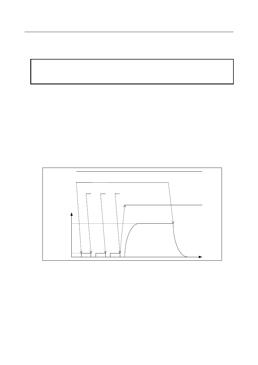
<3>  Step <2> above is repeated until two, three, or four reference marks are detected on the scale. Then, 

the reference position is established, and the reference position established establishment signal 
(ZRF1, ZRF2, ZRF3, etc.) is set to "1". 

<4>  The tool is fed in the direction selected by the feed axis direction selection signal at the jog feedrate. 
 
When the feed axis and direction selection signal is set to "0"  during steps <2> to <4>, feed operation 
stops. When the feed axis direction selection signal  is set to "1"  again, the reference position is 
established. A time chart for the above procedure is shown below. 


Reference mark 

ZRFn 

Feedrate 

FL feedrate 

Time 

JOG feedrate 

JOG 

+Jn(-Jn) 


Fig. 4.10.2 (a)  Time chart for reference position establishment (jog feed) 


  - 

Interruption by the feed axis and direction selection signal 

If the feed axis and direction selection signal +Jn (-Jn) is set to "0"  during reference position 
establishment, the reference position establishment operation is interrupted. In this case, data on the 
reference marks detected through the previous movement is not used for the next reference establishment 
operation. When the feed axis and direction selection signal +Jn (-Jn) is set to "1"  again, the reference 
position establishment operation is resumed, and the reference position is established after two, three, or 
four reference marks are detected. 
 

B-64693EN-1/01


4. REFERENCE POSITION ESTABLISHMENT


- 787 - 

  - 

Interruption by reset or emergency stop 

When a reset or emergency stop is applied during reference position establishment operation, axis 
movement stops, and the reference position establishment operation is interrupted. In this case, data on 
the reference marks detected through the previous movement is not used for the next reference 
establishment operation. When the feed axis and direction selection signal +Jn (-Jn) is set to "1" again, the 
reference position is established after two, three, or four reference marks are detected. 
 

Caution 

  - 

PMC axis control 

The reference position establishment operation is not performed in rapid traverse (axis control command 
00h) or continuous feed (axis control command 06h) under PMC axis control. 
 

  - 

Rapid traverse operation other than G00 

In a rapid traverse operation automatically generated by a command such as canned cycle, no reference 
position establishment operation is carried out. 
 

  - 

Reference position establishment operation   

This function has the same specifications as the conventional function of the distance coded linear scale 
interface, with regard to the operation to detect a reference mark and establish a reference position. The 
parameter setting, limitation, and the like are also the same. 
For details, refer to " Linear scale with distance-coded reference marks (serial)." 
 

Parameter 


#7 

#6 

#5 

#4 

#3 

#2 

#1 

#0 

1802 


DC2x 

DC4x 


[Input type]  Parameter input 


[Data type]  Bit axis 


#1  DC4x

  When the reference position is established on the linear scale with reference marks: 

0: 

An absolute position is established by detecting three reference marks. 

1: 

An absolute position is established by detecting four reference marks. 


#2  DC2x

  Reference  position  establishment  operation  for a linear scale with reference  marks is 

performed as follows: 
0: 

The setting of bit 1 (DC4) of parameter No. 1802 is followed. 

1: 

An absolute position is established by detecting two reference marks. 


NOTE 

1  When this parameter is set to 1, specify the direction of the scale 

zero point by setting bit 4 (SCP) of parameter No. 1817. 

2  When a rotary encoder with absolute address reference marks is 

used, this parameter is invalid. Even when this parameter is set to 
1, the setting of bit 1 (DC4) of parameter No. 1802 is followed. 


#7 

#6 

#5 

#4 

#3 

#2 

#1 

#0 

1815 


DCLx 

OPTx 


[Input type]  Parameter input 


[Data type]  Bit axis 


4. REFERENCE POSITION ESTABLISHMENT


B-64693EN-1/01


- 788 - 

NOTE 


When at least one of these parameters is set, the power must be 
turned off before operation is continued. 


#1  OPTx

  The separate position detector is: 

0: 

Not to be used (semi-closed system) 

1: 

To be used (full-closed system) 


NOTE 


Set 1 when this function is used. 


#2  DCLx

  As a separate position detector, a linear scale with reference marks or a linear scale with 

an absolute address zero point is: 
0: 

Not used. 

1: 

Used. 


NOTE 


Set 1 when this function is used. 


#7 

#6 

#5 

#4 

#3 

#2 

#1 

#0 

1818 


DG0 


[Input type] 

Parameter input


[Data type] 

Bit axis


#2  DG0

  When the linear scale function  with  absolute  address  reference  marks is used, reference 

position establishment operation based on the G00 command and jog feed is: 
0: 

Disabled. 

1: 

Enabled. 


4.11 

REFERENCE POSITION SIGNAL OUTPUT FUNCTION 

Overview 

If, after the establishment of the reference position on each axis, the coordinates in the machine 
coordinate system match the reference position, this function outputs a signal as the DO signal <Fn517> 
of the PMC. 
Also, if the coordinates in the machine coordinate system  match the second reference position, the 
function outputs a signal as the DO signal <Fn518> of the PMC. 
 

Signal 

Reference position match signals RP11 to RP18<Fn517> 

     [Classification]  Output signal 
 

[Function]  Reports that the coordinates in the machine coordinate system match the reference 

position. 
There is an independent one for each axis, with the last digit indicating the number of the 
corresponding controlled axis. 
RP1x 
x :  1 

The machine coordinates on the first axis match the reference position. 


2    The machine coordinates on the second axis match the reference position. 


The machine coordinates on the third axis match the reference position. 

:   : 
:   : 

B-64693EN-1/01


4. REFERENCE POSITION ESTABLISHMENT


- 789 - 


[Output cond.]  This signal becomes "1" only when, after the establishment of the reference position on 

each axis, the coordinates in the machine coordinate system match the reference position. 
 

NOTE 


This signal does not take the delay due to acceleration/deceleration 
into consideration. 
No in-position check is performed. 


Second reference position match signals RP21 to RP28<Fn518> 

     [Classification]  Output signal 
 

[Function]  Reports that the coordinates in the machine coordinate system match the second reference 

position. 
There is an independent one for each axis, with the last digit indicating the number of the 
corresponding controlled axis. 
RP2x 
x :  1 

The machine coordinates on the first axis match the second reference position. 


2    The machine coordinates on the second axis match the second reference 
position. 


The machine coordinates on the third axis match the second reference position. 

:   : 
:   : 


[Output cond.]  This signal becomes "1" only when, after the establishment of the reference position on 

each axis, the coordinates in the machine coordinate system match the second reference 
position. 
 

NOTE 


This signal does not take the delay due to acceleration/deceleration 
into consideration. 
No in-position check is performed. 


Signal address 


#7 

#6 

#5 

#4 

#3 

#2 

#1 

#0 

Fn517 


RP18 

RP17 

RP16 

RP15 

RP14 

RP13 

RP12 

RP11 


Fn518 


RP28 

RP27 

RP26 

RP25 

RP24 

RP23 

RP22 

RP21 


Parameter 


#7 

#6 

#5 

#4 

#3 

#2 

#1 

#0 

1205 


R2O 

R1O 


[Input type]  Parameter input 


[Data type]  Bit path 


#4  R1O

  The output of the signal for the reference position is: 

0: 

Disabled. 

1: 

Enabled. 


#5  R2O

  The output of the signal for the second reference position is: 

0: 

Disabled. 

1: 

Enabled. 


4. REFERENCE POSITION ESTABLISHMENT


B-64693EN-1/01


- 790 - 

NOTE 

NOTE 

1  For an axis subject to angular axis control, a signal is output in the angular 

coordinate system. 

2  For the third/fourth reference positions and floating reference positions, no 

signals are output. 


4.12 

CORRESPONDENCE OF ROTARY SCALE WITHOUT 
ROTARY DATA 

Overview 

This manual describes how to deal with an absolute position detector (absolute pulse coder) or a scale 
with distance-coded reference marks (serial), when the rotary scale without rotary data is used, such as 
Heidenhain rotary scale RCN723 or Futaba rotary scale FRR902L3DB. 
And it is required to set some servo parameters in order to use Heidenhain rotary scale RCN223, 723 and 
220. In the case of using such a scale, please set servo parameters with referring to Subsection 4.14.5 
“Method of using Heidenhain rotary scale RCN223, 723 and 220”. 
 

  WARNING 

Please set the parameters that correspond to the absolute position detector 

which is actually used. If the parameter is not set correctly, the machine 
coordinates are not correctly established at power-on. 


4.12.1 

Setting Method by Rotary Axis Type and Movable Range 

Rotary axis type 

Movable range 

Parameters required setting 

Reference item 

Rotary axis B type 

Under one rotation 

No.1817#3 

No.1868 

Subsec. 4.14.2 

Rotary axis B type 

Over one rotation 

No.1815#0 

Subsec. 4.14.3 

Rotary axis A type 

No.1815#6 

Subsec. 4.14.4 

 
See the following description for the rotary axial type. 
 

Parameter 


#7 

#6 

#5 

#4 

#3 

#2 

#1 

#0 

1006 


ROSx 

ROTx 


[Input type]  Parameter input 


[Data type]  Bit axis 


NOTE 


When at least one of these parameters is set, the power must be 
turned off before operation is continued. 


B-64693EN-1/01


4. REFERENCE POSITION ESTABLISHMENT


- 791 - 


#0  ROTx


#1  ROSx 

Setting linear or rotary axis. 

ROSx  ROTx 

Meaning 

Linear axis 
(1)  Inch/metric conversion is done. 
(2)  All coordinate values are linear axis type. (Is not rounded in 0 to 360

°

(3)  Stored pitch error compensation is linear axis type (Refer to parameter No. 

3624) 

Rotary axis (A type) 
(1)  Inch/metric conversion is not done. 
(2)  Machine coordinate values are rounded in 0 to 360

°

. Absolute coordinate 

values are rounded or not rounded by bits 0 (ROAx) and 2 (RRLx) of 
parameter No. 1008. 

(3)  Stored pitch error compensation is the rotation type. (Refer to parameter No. 

3624) 

(4)  Automatic reference position return (G28, G30) is done in the reference 

position return direction and the move amount does not exceed one rotation. 

Rotary axis (B type) 
(1)  Inch/metric conversion is not done. 
(2)  Machine coordinate values, absolute coordinate values and relative 

coordinate values are linear axis type. (Is not rounded in 0 to 360

°

). 

(3)  Stored pitch error compensation is linear axis type (Refer to parameter No. 

3624) 

(4)  Cannot be used with the rotary axis roll-over function and the index table 

indexing function (M series) 

Except for the 

above. 

Setting is invalid (unused) 


4.12.2 

In the Case of a Rotary Axis B Type whose Movable Range is 
under One Rotation 

In the case of a rotary axis B type whose movable range is under one rotation with an absolute position 
detector (absolute pulse coder) or a scale with distance-coded reference marks (serial), there is an 
uncontinuous point of scale data which is under one rotation, if a rotary scale without data (the number of 
rotation) is used. Then, if the scale data within the movable range of the rotary axis is continuous, it is 
possible to acquire the correct machine coordinate value of NC. On the other hand,  if an uncontinuous 
point of scale data is in movable range, the machine coordinate value of NC is different from correct 
position. 
In this function, by the bit 3 (SCRx) of parameter  No.1817 and parameter  No.1868, the machine 
coordinate value of NC become correct even if an uncontinuous point of scale data is in movable range. 
Therefore, it is possible to set a rotary axis B type even if there is no rotation speed data on the rotary 
scale on the rotary axis whose movable range is under one rotation


4. REFERENCE POSITION ESTABLISHMENT


B-64693EN-1/01


- 792 - 

Example 1 


0

°


180

°


-180

°


Actual machine   

coordinate value 

Scale data 

359999 

135000 

-135

°


-45

°


45

°


Movable range of rotary axis 

180000 

90000 

Machine position of NC 

-45.000

°


45.000

°


Fig. 4.12.2 (a) The case that the scale data is continuous in movable range of rotary axis 

 
In the case of Fig. 4.12.2 (a), the scale data is continuous from 90000 to 18000.   
Because the machine coordinate value of NC is shown by the following equation, (scale data when the 
power is turned on) - (scale data on the machine coordinate value equals 0), the machine coordinate value 
of NC becomes correct ones from -45.000 to 45.000. 


Example 2 


0

°


180

°


-180

°


Actual machine   

coordinate value 


Scale data 


359999 

320000 

40

°


-45

°


45

°


275000 

5000 

Movable range of rotary axis 


Machine position of NC 


-45.000

°

  39.999

°


-320.000

°


-315.000

°


Fig. 4.12.2 (b) The case that the scale data is uncontinuous in movable range of rotary axis. 


In the case of Fig. 4.12.2 (b), the scale data of movable range is uncontinuous, 275000 to 359999 and 0 to 
5000, because the uncontinuous point whose machine coordinate value 40.000 exists.   

B-64693EN-1/01


4. REFERENCE POSITION ESTABLISHMENT


- 793 - 

Because the machine coordinate value of NC is shown by the following equation, (scale data when the 
power is turned on) - (scale data on the machine coordinate value equals 0),   
NC shows two position ranges. One is correct ones from -45.000 to 0.000 to 39.999. And another is 
wrong ones from -320.000 to -315.000, which is different from correct position by 360 degree. 
 

Example 3 


-40000 

-85000 

250000 

Scale data of threshold position 

-45.000

°


45.000

°


Range where scale data is converted 

(present scale 

  360000) 

0

°


Movable range of rotary axis 

Scale data 

Actual mathine   

coordinate value 

Machine position of NC 

5000 

-45

°


45

°


Threshold position   

290

°

 ( -70

°


Fig. 4.12.2 (c) The case that parameter No.1817#3 is set to 1 and No.1868 (the threshold position) 

  is set to 290.0. 

 
In the case of Fig. 4.12.2 (b), if the bit 3 (SCRx) of parameter No. 1817 is set to 1 and No.1868 (threshold 
position) is set to 290.0, the scale data of the threshold position (parameter No.1868) or more (250000 to 
359999) is converted to the data which is subtracted by the amount of one rotation (360000 in this case), 
as shown in Fig. 4.12.2 (c). Therefore, the scale data is continuous as -85000 to 5000 in movable range of 
the rotary axis. The machine coordinate value of NC can become correct value as -45.000 to 45.000 
because the scale data is continuous in movable range of the rotary axis like Example 1.   
The parameter No.1868 (the threshold position) is required to be set the position out of movable range 
and positive value. (0.0 to 360.0: Set to 290.0 instead of –70.0, in this case.) 


Content      ..     102      103      104      105     ..