FANUC Series 0i-MODEL F Plus. CONNECTION MANUAL (FUNCTION) - page 102
 

  Index      Manuals     FANUC Series 0i-MODEL F Plus. CONNECTION MANUAL (FUNCTION) B-64693EN-1/01


Search            copyright infringement  


Content      ..     100      101      102      103     ..


FANUC Series 0i-MODEL F Plus. CONNECTION MANUAL (FUNCTION) - page 102


4. REFERENCE POSITION ESTABLISHMENT


B-64693EN-1/01


- 770 - 

1884 


Distance 2 from the scale zero point to reference position 


NOTE 


When this parameter is set, the power must be turned off before 
operation is continued. 


[Input type]  Parameter input 


[Data type]  2-word axis 


[Unit of data]  Detection unit 

[Valid data range]  -999 to 999 


When a linear scale with absolute address reference marks is used, set the distance from 
the scale zero point to reference position in parameter Nos. 1883 and 1884). 
 

Distance from the zero point to the reference position of a linear scale 
= No. 1884 

×

 1,000,000,000 + No. 1883 

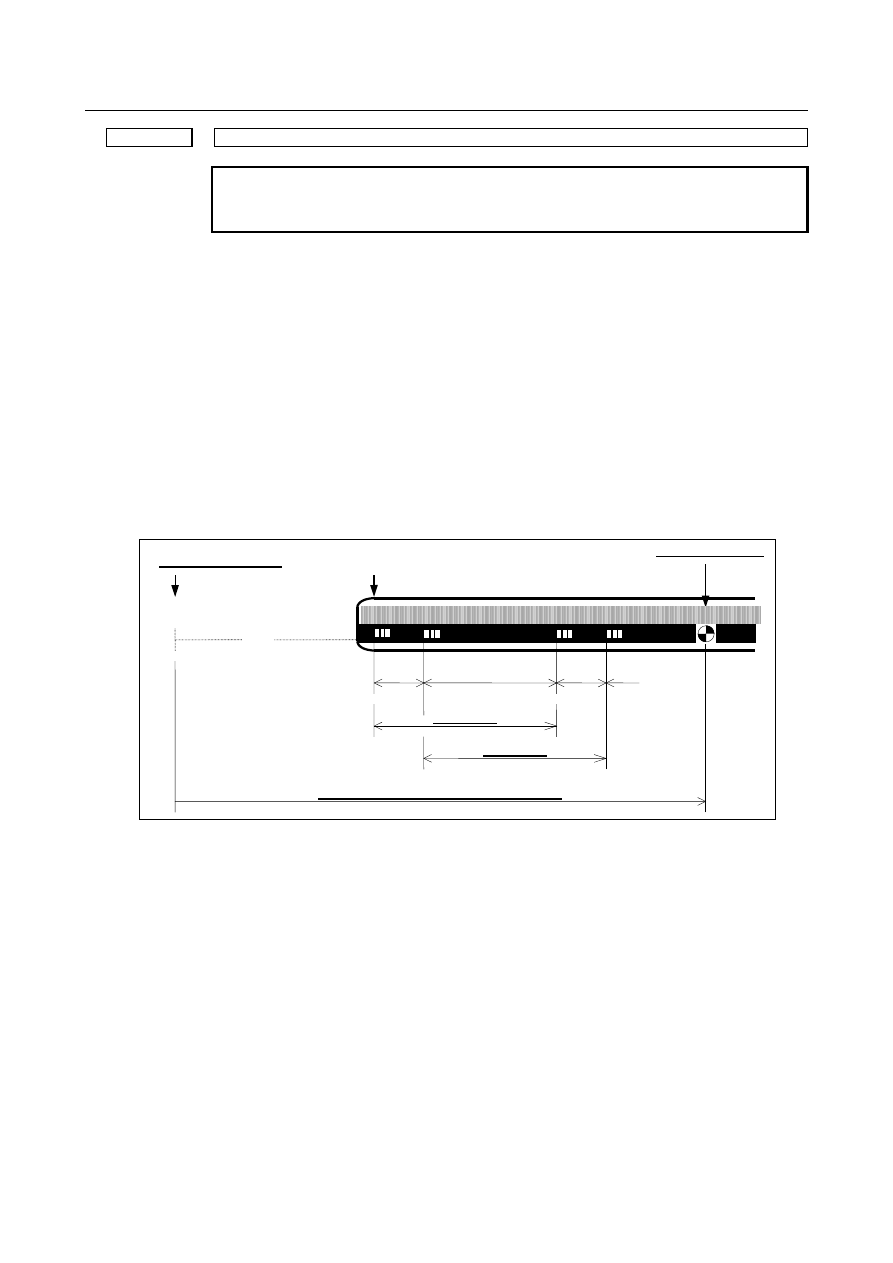
The  scale  zero point  represents  a  point  where mark 1 and mark 2 match. Usually, this 
point  is a virtual point  that does not physically exist on the scale. (See the following 
figure.) 
If the reference position  is placed in the + direction  when viewed from the scale  zero 
point, set a positive value. If the reference position  is placed in the -  direction  when 
viewed from the scale zero point, set a negative value. 


Mark 1 

Mark 2 

Mark 1 

Mark 2 

Zero point of encoder 

Encoder end


Reference position


……..


Mark 1 = mark 2


41.8


8.2


42.0


8.0


PRM.1821


PRM.1882


PRM.1884 

×

 1,000,000,000 + PRM.1883


B-64693EN-1/01


4. REFERENCE POSITION ESTABLISHMENT


- 771 - 

[Example of parameter settings] 
 

When an encoder as shown the following figure is used with an IS-B, millimeter 
machine: 


20.000 

19.980 

9.940 

10.060 

9.960 

10.040 

9.980 

10.020 

5.000 

20.000mm 

20.020mm 

-[9960/(20020-20000)*20000+5000] = 

-9965000


Mark 1 

Mark 2 

Mark 1 

Mark 2 

Mark 1 

Mark 1 

Mark 2 

Mark 1 

Mark 

Mark 2 

Mark 1 = mark 2 

B


A


Scale zero point 

+ direction 

- direction 

Reference 

position 


Parameters 

No.1821 (interval of mark 1)


= 20000 

No.1882 (interval of mark 2)


= 20020 

No.1883 (reference position)        = position of point A + 5.000 
= distance between A and B/(mark 2 

-

 mark 1) 

×

 mark 1 + 5000 

= 9960/(20020-20000) 

×

 20000 + 5000 

= 9965000 
= -9965000 (the reference position is on the negative side) 


[Setting parameter No. 1883] 
When it is difficult to measure the distance  from the scale  zero point  to the reference 
position  (parameter No.  1883), the method  described  below can be used to find the 
distance. 
 
<1>  Set parameter No. 1815 to enable this function. 
 

Set an appropriate value in parameter No. 1821 and No. 1882. 


Parameter No. 1240 is set to 0. 


Parameters Nos. 1883 and 1884 are set to 0. 

<2>  At an appropriate position, establish a reference position. 
 

(As a result, the machine coordinate represents the distance from the scale zero point 
to the current position.) 

<3>  By jog feed or handle feed, place the machine at the accurate reference position. 
<4>  In  parameter No.  1883, set the machine  coordinate  of that time converted  to the 

detection unit (machine coordinate 

×

 CMR). 

<5>  If necessary, set parameter No. 1240. 
 

NOTE 

1  Set parameter Nos. 1883 and 1884 so that the distance from the 

scale zero point to the reference position is within the range from 
-999,999,999,999 to +999,999,999,999. If a value beyond this 
range is set, an alarm DS1448, "ILLEGAL PARAMETER (D.C.S.)", 
is issued. 

2  The scale area on the scale cannot be extended across the scale 

zero point. Make parameter settings not to cause the scale area to 
extend beyond the scale zero point. 


4. REFERENCE POSITION ESTABLISHMENT


B-64693EN-1/01


- 772 - 

Alarm and message 

Number 

Message 

Description 

PS5220 

REFERENCE POINT ADJUSTMENT 
MODE 

In case of distance coded linear scale I/F, the reference 
point auto setting bit 2 (DATx) of parameter No. 1819 is set 
to 1. Move the machine to reference position by manual 
operation and execute manual reference return. 

SV1051 

ILLEGAL SYNCHRONOUS AXIS 

In axis synchronous control, the parameter setting for the 
axis for which distance coded linear scale I/F is used, is 
incorrect. Set the following parameters to the same values 
for the master axis and slave axis. 

Parameter No. 1821 (mark-1 interval) 

Parameter No. 1882 (mark-2 interval) 

Bit 2 (DC2x) and Bit 1 (DC4x) of parameter No.1802 
(the number of marks) 

DS0020 

REFERENCE RETURN INCOMPLETE 

An attempt was made to perform an automatic return to the 
reference position on the perpendicular axis before the 
completion of a return to the reference position on the 
angular axis. 
However, this attempt failed because a manual return to the 
reference position during angular axis control or an 
automatic return to the reference position after power-up 
was not commanded. First, return to the reference position 
on the angular axis, then return to the reference position on 
the perpendicular axis. 

DS0026 

MISMATCH OF ANGULAR AXIS(D.C.S) 

On angular axis control, one of the angular/perpendicular 
axes is the scale with ref-pos, and the other of them is not 
the scale with ref-pos. Such system is not admired. 

DS0027 

MISMATCH OF SYNCHRONOUS 
AXIS(D.C.S) 

Master/slave axes of axis synchronous control, one of 
them is the linear scale with distance-coded reference 
marks, and the other of them is not the linear scale with 
distance-coded reference marks. Please establish 
reference position with the input signal 
SYNCn<Gn138>, SYNCJn<Gn140> or parameter 
setting to 0. 

The slave axis of the axis synchronous control is two or 
more settings. Such system is not admired. 

DS1448 

ILLEGAL PARAMETER (D.C.S.) 

The setting value of parameter for distance coded linear 
scale I/F is satisfied the following any conditions.   

The absolute-position detection function is enabled. 

Either parameter No. 1821 (mark-1 interval) or 
parameter 1882 (mark-2 interval) is set to 0. 

Parameters Nos. 1821 and 1882 have identical 
settings. 

The difference between the settings made for 
parameters Nos. 1821 and 1882 is greater than or 
equal to twice either setting. 

The setting value of parameters 1883 and 1884 are 
over the valid data range. 

In case of Rotary axis (B type), the values other than 0 
are set to the parameter No.1868 and No.1869 or bit 0 
(RVSx) of parameter No.1815 is set to 1. 

DS1449 

REFERENCE MARK ARE DIFFERENT 
FROM PARAMETER 

In case of distance coded linear scale I/F, the actual 
interval of reference marks is different from setting value in 
parameters Nos. 1821 and 1882. 


B-64693EN-1/01


4. REFERENCE POSITION ESTABLISHMENT


- 773 - 

Diagnosis data 

3545 


Measurement point 1 of the reference marks of distance coded linear scale 


3546 


Measurement point 2 of the reference marks of distance coded linear scale 


3547 


Measurement point 3 of the reference marks of distance coded linear scale 


3548 


Measurement point 4 of the reference marks of distance coded linear scale 


[Data type] 

2-word axis


[Unit of data]  Detection unit 


[Valid data range]  -999999999 to 999999999 


3549 


Internal status of the reference marks of distance coded linear scale 


3550 


Scale counter value of the reference marks of distance coded linear scale 


[Data type] 

2-word axis


[Unit of data]  Detection unit 


[Valid data range]  -999999999 to 999999999 


3551 


Scale counter value of the reference marks of distance coded linear scale (high) 


[Data type] 

2-word axis


[Unit of data]  Detection unit 


[Valid data range]  -999 to 999 

 
Scale counter value of the reference marks of distance coded linear scale = diagnosis data 
No.3551 

×

 1,000,000,000 + diagnosis data No.3550 


4.9 

LINEAR SCALE WITH DISTANCE-CODED REFERENCE 
MARKS (SERIAL) 

Overview 

By using High-resolution serial output circuit for the linear scale with distance-coded reference marks 
(serial), the CNC measures the interval of referenced mark by axis moving of short distance and 
determines the absolute position. 
This function enables high-speed high-precision detection by using High-resolution serial output circuit. 
It is available that using maximum stroke 30 meters length. 
 

Explanation 

The linear scale with distance-coded reference marks (serial) is combined the irregular reference marked 
linear scale with the High-resolution serial output circuit, it can detect the accurate position. 


Reference mark signal 

10.02 

10.04 

10.06 

20 

40 

60 


The CNC measures the interval of referenced mark by axis moving of short distance and determines the 
absolute position, because of the interval of each reference mark is different with regular interval. 

4. REFERENCE POSITION ESTABLISHMENT


B-64693EN-1/01


- 774 - 

It is not necessary that the axis is moved to the reference position for establishment of reference position. 
 
This function enables high-speed high-precision detection by using High-resolution serial output circuit. 
It is available that using maximum stroke 30 meters length. 
 

  - 

Connection 

It is available under linear motor system and full closed system. 


Linear motor system 

CNC 

Servo 

amplifier 

Linear motor 

Linear Motor 

Position Detection 

Circuit C 

Pole sensor 

Linear scale with distance-coded 

reference marks (serial) 

CNC 

Servo 

amplifier 

Separate 

Detector 

Interface 

Unit 

Table 

High 

Resolution 

Serial Output 

Circuit C 

Full Closed System 

Linear scale with distance-coded 

reference marks (serial type) 


  - 

Procedure for reference position establishment through manual operation 

(1)  Select the JOG mode, and set the manual reference position return selection signal ZRN to "1".   
(2)  Set the feed axis and direction selection signal (+J1, -J1, +J2, -J2, …) of a target axis to “1” and feed 

toward the reference position. 

(3)  The axis is fed at a constant low speed (reference position return FL feedrate specified by parameter 

No.1425 setting). 

(4)  When the absolute position of linear scale with distance-coded reference marks (serial) is detected, 

the axis stops. Then the absolute position of CNC is calculated and the reference position 
establishment signal (ZRF1, ZRF2, ZRF3, …) turns to "1".   

 
The timing chart for this procedures is given below. 


FL rate 

JOG 

ZRN 

+J1 

Reference mark 

ZRF1 

Feedrate 


B-64693EN-1/01


4. REFERENCE POSITION ESTABLISHMENT


- 775 - 

Procedure for reference position establishment through automatic operation 

If an automatic reference position return (G28) is specified before a reference position is not established, 
steps (3) to (4) above are performed automatically. 
After the reference position is established, the automatic reference position return is performed by setting 
of bit 0 (RFS) of parameter No. 1818. 
 

  - 

Stopping the operation for establishing a reference position 

The operation for establishing a reference position is stopped if any of 
the following operations is performed in steps (3) to (4), described above. 


Reset 


Setting the feed axis and direction selection signal (+J1, -J1, +J2, -J2, etc.) to "0" 


Setting the Servo off signals (SVF1, SVF2, etc.) to "1" 

If any of the following operations is performed during the operation of automatic reference position 
return (G28) before a reference position is not established, the operation for establishing a reference 
position stops: 


Reset 


Performing feed hold during movement from an intermediate position to the reference position 


Setting the Servo off signals (SVF1, SVF2, etc.) to "1" 

If the operation for establishing a reference position is stopped by an operation other than a reset, the 
operation for establishing a reference position must be reset and resumed. 
 

  - 

Establishing a reference position and moving to the reference position 

By following operation, establishing a reference position and moving to the reference position is 
performed. 


Moving through manual 

operation in REF mode 

Moving through automatic operation by automatic 

reference position return (G28) 

The reference 
position is not 
established. 

Establishing the reference 
position 

Firstly, moving to the intermediate position, and 
establishing the reference position. 
Secondly, whether moving to the reference position or not 
is performed by setting bit 0 (RFS) of parameter No.1818. 

The reference 
position is 
established. 

Moving to the reference position 

Whether moving to the intermediate position and the 
reference position or not is performed by setting bit 1 
(RF2) of parameter No.1818. 


  - 

Axis synchronous control 

In case of using the axis synchronous control, please confirm the following items. 


When this function is used with axis synchronous control axes, the linear scale with distance-coded 
reference marks (serial) used for the master axis and that used for the slave axis must have reference 
marks placed at identical intervals. 


The linear scale with distance-coded reference marks (serial) can be installed on the master and slave 
axes either in the same or opposite direction. 


To the axis parameters, which relate to this function (except No.1883, No.1884) (distance from the 
scale zero point  to reference position), the same value must be set for the master axis and for the 
slave axis. 


The linear scale with distance-coded reference marks (serial) should be applied for the master axis 
and the slave axis. 
If either of the master axis or the slave axis is not the linear scale with distance-coded reference 
marks (serial), alarm DS0018, "SERIAL DCL:MISMATCH (SSYNC CTRL)", occurs when 
reference position establishment is tried by the axis synchronous control. 


During operating the establishment of reference position, the state of synchronous control axis 
selection signals (SYNCn<Gn138> or SYNCJn<Gn140>) should be kept. 


4. REFERENCE POSITION ESTABLISHMENT


B-64693EN-1/01


- 776 - 

Both of synchronous axes (master axis and slave axis) are fed on the reference position return FL feedrate 
until distance coded scales of both axes detect the absolute position.   
Then absolute position of both axes are calculated and the reference position establishment signal (ZRF1, 
ZRF2, ...) turn to "1". 

NOTE 


When this function is used by the axis synchronous control, only one axis is 
available for the slave axis. 


  - 

Angular axis control 

In case of using the angular axis control, please confirm the following items. 


It is necessary to use the linear scale with distance-coded reference marks (serial) for both the 
perpendicular axis and the angular axis. 
If not, the alarm DS0019, "2SERIAL DCL:MISMATCH(ANGL-AXIS)", occurs when reference 
position establishment is commanded. 


Please set so that whenever  the reference position establishment of angular axes is  tried, 
perpendicular  axes are fed (bit 2 (AZR) of parameter No. 8200 to 0 and input signal NOZAGC 
<G063.5> to "0"). 
If not, the alarm DS0019 occurs when reference position establishment is commanded. 


When the reference point of the perpendicular axis is established, it is necessary to establish the 
reference point of the angular axis previously. When the perpendicular axis is commanded 
previously or the perpendicular axis and the angular axis are commanded simultaneously, the alarm 
DS0020, "REFERENCE RETURN INCOMPLETE", occurs. 


On angular axis control, if you use automatic setting of parameter Nos.1883 and 1884 on reference 
position establishment (bit 2 (DATx) of parameter No.1819=1) for both the perpendicular axis and 
the angular axis, please establish reference point of perpendicular axis after reference position auto   
establishment and return of angular axis. 

 
In manual reference position return, the perpendicular axis cannot be specified while the angular axis 
reference point is being established. The perpendicular axis, if specified, is ignored. 
 

Parameters 


#7 

#6 

#5 

#4 

#3 

#2 

#1 

#0 

1815 


DCLx 

OPTx 


[Input type]  Parameter input 


[Data type]  Bit axis 


NOTE 


When at least one of these parameters is set, the power must be 
turned off before operation is continued. 


#1  OPTx

  The separate position detector is: 

0: 

Not to be used (semi-closed system) 

1: 

To be used (full-closed system) 


NOTE 


Set this parameter to 1 when using a linear scale with 
distance-coded reference marks (serial) (full-closed system). 


#2  DCLx

  As a separate position detector, a linear scale with reference marks or a linear scale with 

an absolute address zero point is: 
0: 

Not used. 

B-64693EN-1/01


4. REFERENCE POSITION ESTABLISHMENT


- 777 - 

1: 

Used. 


#7 

#6 

#5 

#4 

#3 

#2 

#1 

#0 

1818 


SDCx 


RF2x 

RFSx 


[Input type] 

Parameter input


[Data type] 

Bit axis


#0  RFSx

  If G28 is specified for an axis for which a reference position is not established (ZRF = 0) 

when a linear scale with an absolute address zero point is used: 
0: 

A movement is made to the reference position after reference position establishment 
operation. 

1: 

No movement is made after reference  position  establishment  operation, but the 
operation is completed. 


NOTE 


This parameter disables movement based on the G28 command to 
a reference position. So, use this parameter only in special cases. 


#1  RF2x

  If G28 is specified for an axis for which a reference position is already established (ZRF 

= 1) when a linear scale with an absolute address zero point is used: 
0: 

A movement is made to the reference position. 

1: 

No movement is made to the intermediate position  and  reference  position, but the 
operation is completed. 


NOTE 


This parameter disables movement based on the G28 command to 
a reference position. So, use this parameter only in special cases. 


#3  SDCx

  A linear scale with an absolute address zero point is: 

0: 

Not used. 

1: 

Used. 


NOTE 

1  When the parameter SDCx is set, the power must be turned off 

before operation is continued. Alarm PW0000, “POWER MUST BE 
OFF ” does not occur. 

2  Please set bit 1 (SDC) of parameter No. 1815 to 1 when the full 

closed system. But please set this parameter to 0 when the Linear 
motor system.   


#7 

#6 

#5 

#4 

#3 

#2 

#1 

#0 

1819 


DATx 


[Input type] 

Parameter input


[Data type] 

Bit axis


#2  DATx

  The  automatic  setting  of  parameters  Nos.  1883  and  1884  at manual reference  position 

return time is: 
0: 

Not performed. 

1: 

Performed. 


Content      ..     100      101      102      103     ..