FANUC Series 0i-MODEL F Plus. CONNECTION MANUAL (FUNCTION) - page 101
4. REFERENCE POSITION ESTABLISHMENT
B-64693EN-1/01
- 762 -
-
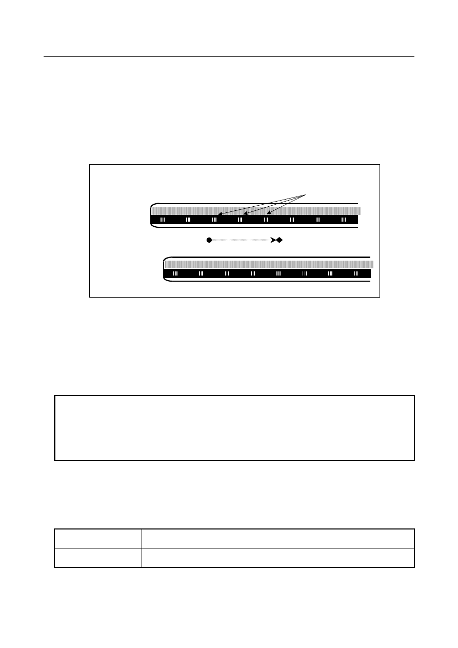
Reference position establishment with axis synchronous control axes
With axis synchronous control axes, a reference position is established as follows. When a reference mark
for the master or slave axis is detected, a stop takes place temporarily. Then, a feed operation is
performed again at the reference position return FL feedrate. This sequence is repeated until a reference
mark is detected for both the master and slave axes. Then the absolute position is calculated for both the
master and slave axes, and the reference position establishment signal (ZRF1, ZRF2, ...) are set to 1.
After the reference position has been established by the above operation, a synchronization error is
corrected. (Checking for excessive synchronization error alarm 2 is made even during reference position
establishment.)
Scale end
Reference mark
(1)
(2)
(3)
(a)
(b)
(c)
Master axis
Slave axis
Start point
End Point
(Example of 3 points measurement system)
In the above example, the following sequence is executed.
a.
When the reference mark (1) of the master axis is detected, both master axis and slave axis stop.
b.
Both the axes begin to move again at a reference position return FL feedrate.
c.
When the reference mark (a) of the slave axis is detected, both axes stop again.
d.
Both the axes begin to move again at FL feedrate.
e.
Both axes repeat the operation until all point ((2) -> (b) ->(3)) are detected.
f.
When the slave axis detects the third reference mark (c), both the axes end the reference position
establishment.
NOTE
In case of this function is used with axis synchronous control axes, if the value of
parameters Nos. 1883 and 1884 (Distance 1, 2 from the scale zero point to
reference position) for both the master and slave axes is 0, the reference
position is not established. Also, the reference position establishment signals
(ZRF1, ZRF2, ...) are not set to "1".
-
PMC control axis
In PMC axis control, if the reference position return command (axis control command code 05H) is issued for
an axis having a distance coded linear scale, reference position return is performed according to the reference
position return sequence for the distance coded linear scale.
Specifically, the following operations take place:
Before reference position
establishment
The reference position is established by detecting two, three or four reference marks.
Movement to the reference position is not performed.
After reference position
establishment
Positioning at the reference position is performed.
-
Arbitrary angular axis control
There are the following limitations when the angular axis control is used.