FANUC Series 0i-MODEL F Plus. CONNECTION MANUAL (FUNCTION) - page 99
4. REFERENCE POSITION ESTABLISHMENT
B-64693EN-1/01
- 746 -
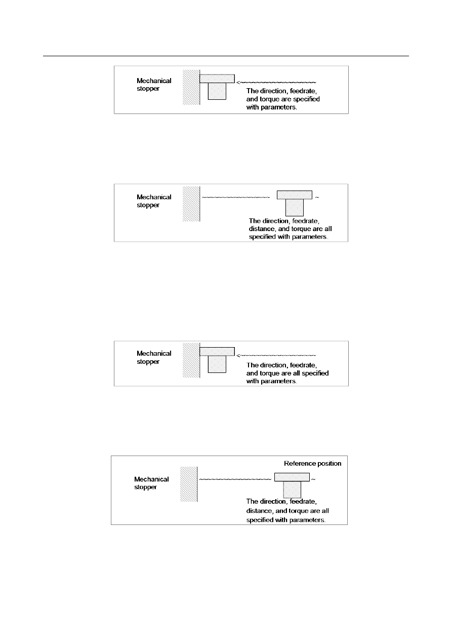
(B) After the tool strikes the mechanical stopper, the tool is withdrawn in the direction opposite to the
butting direction, along the axis for a parameter-set distance.
-
The tool is moved in the direction opposite to that specified with bit 5 (ZMIx) of parameter
No.1006,
-
At the feedrate specified with parameter No.7185,
-
For the distance specified with parameter No.7181.
(C) Operations (D) and (E) are performed from the withdrawal point, such that the tool is butted against
the mechanical stopper at a constant feedrate in reference position setting.
(D) The tool moves along the specified axis at a specified torque until it butts against the mechanical
stopper.
-
The tool moves in the direction specified with bit 5 (ZMIx) of parameter No.1006,
-
At the feedrate specified with parameter No.7184,
-
At the torque specified with parameter No.7186 or No.7187 (until the tool strikes the
mechanical stopper).
(E) After the tool strikes the mechanical stopper end on the axis, the tool is withdrawn in the direction
opposite to the butting direction, along the axis for a parameter-set distance.
-
The tool is moved in the direction opposite to that specified with bit 5 (ZMIx) of parameter
No.1006,
-
At the feedrate specified with parameter No. 7185,
-
For the distance specified with parameter No.7182.
For parameter No.7183 and No.7184, set the feedrates at which the tool is moved toward the mechanical
stopper with a limited torque, considering the machine accuracy.
After the tool strikes the mechanical stopper, and the tool is withdrawn the distance specified with
parameter No.7182, the withdrawal point is set as the reference position on the specified axis. Then, the
reference position return end signal and reference position establishment signal are set to 1.
The timing chart for the cycle operation is shown below.