FANUC Series 0i-MODEL F Plus. CONNECTION MANUAL (FUNCTION) - page 93
 

  Index      Manuals     FANUC Series 0i-MODEL F Plus. CONNECTION MANUAL (FUNCTION) B-64693EN-1/01


Search            copyright infringement  


Content      ..     91      92      93      94     ..


FANUC Series 0i-MODEL F Plus. CONNECTION MANUAL (FUNCTION) - page 93


3. MANUAL OPERATION


B-64693EN-1/01


- 698 - 

19697 


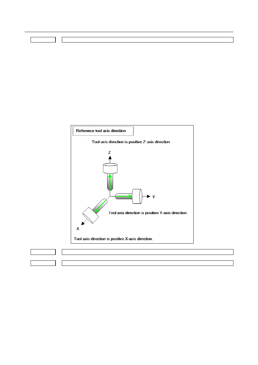
Reference tool axis direction 


[Input type]  Parameter input 


[Data type]  Byte path 

[Valid data range]  0 to 3 

Set the tool axis direction in the machine coordinate system when the rotation axes for 
controlling the tool are all at 0 degrees.  Also, set the tool axis direction in the machine 
coordinate system in a mechanism in which only the rotation axes for controlling the 
table are present (there is no rotation axis for controlling the tool). 
1: 

Positive X-axis direction 

2: 

Positive Y-axis direction 

3: 

Positive Z-axis direction 

When the reference tool axis direction is neither the X-, Y-, nor Z-axis direction, set the 
reference direction in this parameter, then set appropriate angles as the reference angle 
RA and reference angle RB (parameters Nos. 19698 and 19699). 


19698 


Angle when the reference tool axis direction is tilted (reference angle RA) 


19699 


Angle when the reference tool axis direction is tilted (reference angle RB) 


[Input type]  Parameter input 


[Data type]  Real path 


[Unit of data]  deg 

[Min. unit of data]  Depend on the increment system of the reference axis 
[Valid data range]  9 digit of minimum unit of data (refer to standard parameter setting 

(When the increment system is IS-B, -999999.999 to +999999.999) 
When the reference tool axis direction (parameter No. 19697) is set to 1, the tool axis is 
tilted the RA degrees on the Z-axis from the positive X-axis direction to positive Y-axis 
direction, then the tool axis is tilted the RB degrees on the X-axis from the positive 
Y-axis direction to positive Z-axis direction. 

B-64693EN-1/01


3. MANUAL OPERATION


- 699 - 

When the reference tool axis direction (parameter No. 19697) is set to 2, the tool axis is 
tilted the RA degrees on the X-axis from the positive Y-axis direction to positive Z-axis 
direction, then the tool axis is tilted the RB degrees on the Y-axis from the positive Z-axis 
direction to positive X-axis direction. 
When the reference tool axis direction (parameter No. 19697) is set to 3, the tool axis is 
tilted the RA degrees on the Y-axis from the positive Z-axis direction to positive X-axis 
direction, then the tool axis is tilted the RB degrees on the Z-axis from the positive X-axis 
direction to positive Y-axis direction. 


19700 


Rotary table position (X-axis of the basic three axes) 


19701 


Rotary table position (Y-axis of the basic three axes) 


19702 


Rotary table position (Z-axis of the basic three axes) 


[Input type]  Parameter input 


[Data type]  Real path 


[Unit of data]  mm, inch (machine unit) 

[Min. unit of data]  Depend on the increment system of the applied axis 
[Valid data range]  9 digit of minimum unit of data (refer to standard parameter setting table (A)) 

(When the increment system is IS-B, -999999.999 to +999999.999) 
Set these parameters when parameter No. 19680 is set to 12 or 21. The vector from the 
origin of the machine coordinate system to point A on the first rotation axis of the table is 
set as the rotary table position in the machine coordinate system. 


3. MANUAL OPERATION


B-64693EN-1/01


- 700 - 

NOTE 


As point A, set a position that is easy to measure on the first rotary 
axis of the table. 


Set a radius value. 


If the rotary table is moved along the X-, Y-, or Z-axis or all of these 
axes, set the position of the rotary table when the machine 
coordinates of the X-, Y-, and Z-axes are all set to 0. 


19703 


Intersection offset vector between the first and second rotation axes of the table (X-axis of the basic 

three axes) 


19704 


Intersection offset vector between the first and second rotation axes of the table (Y-axis of the basic 

three axes) 


19705 


Intersection offset vector between the first and second rotation axes of the table (Z-axis of the basic 

three axes) 


[Input type]  Parameter input 


[Data type]  Real path 


[Unit of data]  mm, inch (machine unit) 

[Min. unit of data]  Depend on the increment system of the applied axis 
[Valid data range]  9 digit of minimum unit of data (refer to standard parameter setting table (A)) 

(When the increment system is IS-B, -999999.999 to +999999.999) 
Set these parameters when the first rotation axis and second rotation axis of the table do 
not intersect. These parameters are valid when parameter No. 19680 is set to 12. When 
the rotation axes for controlling the table are all at 0 degrees, the vector from point A to 
point B on the second rotation axis of the table is set as the intersection offset vector in 
the machine coordinate system. 


NOTE 


As point B, set a position that is easy to measure on the second 
rotary axis of the table. 


Set a radius value. 


19709 


Intersection offset vector between the tool axis and tool rotation axis (X-axis of the basic three axes) 


19710 


Intersection offset vector between the tool axis and tool rotation axis (Y-axis of the basic three axes) 


B-64693EN-1/01


3. MANUAL OPERATION


- 701 - 

19711 


Intersection offset vector between the tool axis and tool rotation axis (Z-axis of the basic three axes) 


[Input type]  Parameter input 


[Data type]  Real path 


[Unit of data]  mm, inch (machine unit) 

[Min. unit of data]  Depend on the increment system of the applied axis 
[Valid data range]  9 digit of minimum unit of data (refer to standard parameter setting table (A)) 

(When the increment system is IS-B, -999999.999 to +999999.999) 
Set these parameters when the tool axis and tool rotation axis do not intersect. 
These parameters are valid when parameter No. 19680 is set to 2 or 21. 
If parameter No. 19680 is 21, set the vector from point D on the tool axis to point E 
determined on the tool rotation axis as the intersection offset vector in the machine 
coordinate system when the rotation axes for controlling the tool are all at 0 degrees. 
If parameter No. 19680 is 2, set the vector from point D on the tool axis to point E 
determined on the second rotation axis of the tool as the intersection offset vector in the 
machine coordinate system when the rotation axes for controlling the tool are all at 0 
degrees. 


NOTE 


Point D is determined by adding the tool length offset and tool 
holder offset (parameter No. 19666) to the tool tip. As point E, set a 
position that is easy to measure. 


Set a radius value. 


19712 


Intersection offset vector between the second and first rotation axes of the tool (X-axis of the basic 

three axes) 


19713 


Intersection offset vector between the second and first rotation axes of the tool (Y-axis of the basic 

three axes) 


19714 


Intersection offset vector between the second and first rotation axes of the tool (Z-axis of the basic 

three axes) 


[Input type]  Parameter input 


[Data type]  Real path 


[Unit of data]  mm, inch (machine unit) 

[Min. unit of data]  Depend on the increment system of the applied axis 
[Valid data range]  9 digit of minimum unit of data (refer to standard parameter setting table (A)) 

(When the increment system is IS-B, -999999.999 to +999999.999) 
Set these parameters when the rotation axes of the tool do not intersect. 
These parameters are valid when parameter No. 19680 is set to 2. 

3. MANUAL OPERATION


B-64693EN-1/01


- 702 - 

Set the vector from point E on the second rotation axis of the tool to point F on the first 
rotation axis of the tool as the intersection offset vector in the machine coordinate system 
when the rotation axes for controlling the tool are all at 0 degrees. 


NOTE 


As point F, set a position that is easy to measure. 


Set a radius value. 


#7 

#6 

#5 

#4 

#3 

#2 

#1 

#0 

19746 


LOZ 

LOD 


[Input type]  Parameter input 


[Data type]  Bit path 


#2  LOD

  As the tool length for 3-dimensional machining manual feed: 

0: 

The value of parameter No. 12318 is used. 

1: 

The tool length currently used for tool length compensation is used. 


#3  LOZ

  When bit 2 (LOD) of parameter No. 19746 is set to 1 and tool length compensation is not 

applied, as the tool length for 3-dimensional machining manual feed: 
0: 

The value of parameter No. 12318 is used. 

1: 

0 is used. 


Note 

NOTE 

1  To perform a 3-dimensional handle feed, the manual handle feed function is 

required. To perform a 3-dimensional handle interrupt, the manual handle 
interrupt function is required. 

2  When a 3-dimensional handle interrupt is performed, rotation axis command 

execution must not be in progress in automatic operation. 

3  When the manual reference position return mode is selected, 3-dimensional 

manual feed is not enabled. 

4  If interlock for each axis is enabled to at least one of 3-dimensional manual feed 

axes, movement with manual feed is not performed. 

B-64693EN-1/01


3. MANUAL OPERATION


- 703 - 

NOTE 

5  When the offset value specified for the tool length offset function is used for tool 

center point rotation feed (when bit 2 (LOD) of parameter No. 19746 is set to 1), 
the controlled point should generally be shifted. (Set bit 5 (SVC) of parameter 
No. 19665 to 1.) 
In this case, specify the tool length with a radius value. 

6  The feed direction of a 3-dimensional handle interrupt is updated as follows. 
 

(a) When bit 7 (PRA) of parameter No. 12319 is set to 0 


It is updated when one of the following operation is executed. 


- The mode of NC (ex, MEM or HANDLE) is changed. 


- Reset is executed. 


- The state of manual handle interrupt axis selection signals (HS1IA to HS1ID 


  <Gn041.0 to 3>, HS1IE<Gn411.4> in case of manual pulse generator No.1) 


  is changed. 


- 3-dimensional manual feed turns enabled or disabled. 

(b) When bit 7 (PRA) of parameter No. 12319 is set to 1 


It is always updated. 


Alarm and message 

No. 

Message 

Description 

PS5459 

MACHINE PARAMETER INCORRECT 

A machine configuration parameters Nos.19665 to 19667 
or Nos.19680 to 19744 is illegal. 


Reference item 

Manual name 

Item name 

OPERATOR’S MANUAL (B-64694EN) 

3-dimensional manual feed 


4. REFERENCE POSITION ESTABLISHMENT


B-64693EN-1/01


- 704 - 

REFERENCE POSITION ESTABLISHMENT 

4.1 

MANUAL REFERENCE POSITION RETURN 

Overview 

The tool is moved in the direction specified by bit 5 (ZMI) of parameter No. 1006 setting the feed axis 
and  direction select signal to 1 during manual reference position return mode. Movement will continue 
until the reference position is obtained. 
Manual reference position return is performed by using a grid method. The reference position is based on 
an electrical grid, using on one-rotation signals received from the position detector. 
 
The following signals relate with the manual reference position return: 


Manual reference position return


Mode selection 

MD1, MD2, MD4 

Selection of reference position return 

ZRN, MREF 

Selection of axis to be moved 

+J1, -J1, +J2, -J2, +J3, -J3, ... 

Selection of direction to be moved 
Selection of speed to be moved 

ROV1, ROV2 

Deceleration signals for reference position return 

*DEC1, *DEC2, *DEC3, ... 

Completion signals for reference position return 

ZP1, ZP2, ZP3, ... 

Reference position establishment signals 

ZRF1, ZRF2, ZRF3, ... 


  - 

Workpiece coordinate system setting/automatic coordinate system setting 

When the workpiece coordinate system is enable (bit 0 (NWZ) of parameter No.8136 is 0), the workpiece 
coordinate system is set upon the completion of manual reference position return.   
 
When the workpiece coordinate system is disable  (bit 0 (NWZ) of parameter No.8136  is 0), and bit 0 
(ZPR) of parameter No. 1201 is set to 1, the coordinate system is preset automatically after the manual 
reference position return. 
Parameter 1250 can be used to set the workpiece coordinate system, upon the completion of reference 
position return. The value set in the parameter sets the reference point of the tool holder or the tip position 
of the reference tool. 
This operation is performed as if the following command were specified at the reference position: 
 

G92X

a

Y

b

Z

γ

 ; 


NOTE 


Automatic coordinate system setting is not performed if the 
workpiece coordinate system is enable (bit 0 (NWZ) of parameter 
No.8136 is 0). In this case, manual reference position return always 
establishes a workpiece coordinate system based on the workpiece 
origin offsets, specified with parameters Nos. 1220 to 1226. 


Explanation 

  - 

Basic procedure for manual reference position return 

<1>  Select manual continuous feed (JOG) mode, and the manual reference position return selection 

signal ZRN to 1. 

<2>  Feed a target axis toward the reference position by setting an appropriate feed axis and direction 

selection signal (+J1, -J1, +J2, -J2,…) to 1. 

B-64693EN-1/01


4. REFERENCE POSITION ESTABLISHMENT


- 705 - 

<3>  While the feed axis and direction selection signal is 1, rapid traverse takes place along that axis. 

Although the rapid traverse override signals (ROV1, ROV2) are valid, the override is generally set 
to 100%. 

<4>  When the reference position is approached, a limit switch installed on the machine is activated, 

making the deceleration signal for reference position (*DEC1, *DEC2, *DEC3,…) to 0. 
Consequently, the feedrate is decelerated to 0, then the tool is fed at a constant low speed (reference 
position return FL feedrate specified by parameter No. 1425 setting). 

<5>  When the deceleration signal returns to 1 again after the limit switch is passed, the tool is continues 

to feed, until the tool stops at the first grid point (electric grid point). 

<6>  Upon confirmation that the current position is at the in-position area, the reference position return 

end signal (ZP1, ZP2, ZP3,…) and the reference position establishment signal (ZRF1, ZRF2, 
ZRF3,…) turn to 1. 

 
These steps are repeated for each axis.   
The number of simultaneously controlled axes is usually one, but it becomes three by setting bit 0 (JAX) 
of parameter No. 1002. 
If the feed axis direction selection signal (+J1, -J1, +J2, -J2,…) turns to 0 between step (2) and (5) , the 
tool is stopped at once, and reference position return is canceled. If the signal turn to 1 again, operation 
resumes from step (3) (rapid traverse). 
 
The timing charts for the basic procedures are given below. 


Rapid traverse rate 

FL rate 

. . . . . . . . . . . . . . . .    .    .    . 


JOG mode or 
TEACH   
IN JOG mode 
 
ZRN 
 
+J1 
 
*DEC1 
 
Grid 
 
ZP1 
 
ZRF1 
 
 
Feedrate 


NOTE 


Grid is not a signal between PMC and CNC. 


Content      ..     91      92      93      94     ..