FANUC Series 0i-MODEL F Plus. CONNECTION MANUAL (FUNCTION) - page 94
 

  Index      Manuals     FANUC Series 0i-MODEL F Plus. CONNECTION MANUAL (FUNCTION) B-64693EN-1/01


Search            copyright infringement  


Content      ..     92      93      94      95     ..


FANUC Series 0i-MODEL F Plus. CONNECTION MANUAL (FUNCTION) - page 94


4. REFERENCE POSITION ESTABLISHMENT


B-64693EN-1/01


- 706 - 

  - 

Installation conditions for deceleration limit switch 

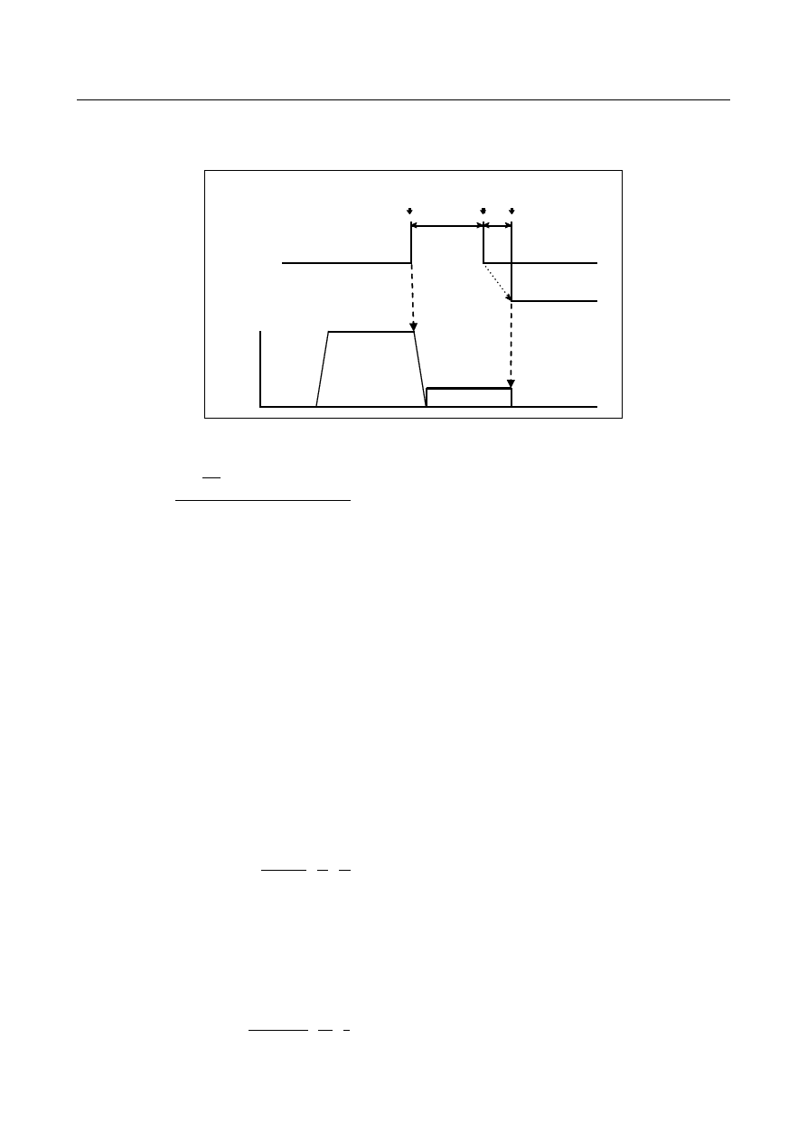
When installing the deceleration limit switch for manual reference position return, ensure that following 
conditions are satisfied: 


*DEC1 
 
 
Grid 
 
Feedrate 


Rapid traverse 
rate (VR) 


Deceleration limit 
operation position 


FL rate (VL) 


.  .  .  .  .  .   .     .     .  


LDA 


LDW 


Reference position 


Deceleration 
limit release 
position 


(1)  LDW : Deceleration dog width [mm, inch] 

LDW

VR

TR

TS

VL TS

>

+

+

+

×

×







2

30

4

60

1000


VR  : Rapid traverse [mm/min, inch/min] 
TR  : Rapid traverse time constant [ms] 
TS  : Servo time constant [ms] 
VL  : FL speed for reference position return [mm/min, inch/min] 

 
(2)  LDA: 

Distance between deceleration limit switch released position and reference position 


LDA = Move amount of 1/2 revolution of motor 

Since the above conditions do not include the limit switch operation variations, this point must also be 
considered at installation. 
 

  - 

Servo position error and one-rotation signal 

To perform the first manual reference position return after power on, the tool must be fed in manual 
reference position return mode, in the reference position return direction at a speed so that the servo 
position error exceeds the value set in parameter No. 1836. At that time, the tool must cross the grid line 
corresponding to a one-rotation signal from the position detector. 
By the above operation, an electrical grid is established based on one-rotation signals from the position 
detector. 
 
The servo position error is calculated from the following formula: 

U

G

F

1

1

60

1000

amount

error 

position 


Servo

×

×

×

=


F : Feedrate [mm/min] 
G : Servo loop gain [s-1] 
U : Detection unit [

µ

m] 

 
(Example) 
 

When the tool is fed at a feedrate F of 6000 mm/min with a servo loop gain G of 30 [s

-1

] and a 

detection unit U of 1 [

µ

m], the servo position error is calculated as follows: 


1

1

30

1

60

1000

6000

error 

position 


Servo

×

×

×

=

  = 3333 


B-64693EN-1/01


4. REFERENCE POSITION ESTABLISHMENT


- 707 - 


By reversing the formula above, the following formula gives the feedrate F needed to obtain a servo 
position error of 128, when the servo loop gain G is 30 [s

-1

] and the detection unit U is 1 [

µ

m]: 


F

=

×

×

128

60

1000

30

  = 230 [mm/min] 


Therefore, when the servo loop gain is 30 [s

-1

], the detection unit is 1 [

µ

m], and parameter No. 1836 

is set to 128, the tool must be fed in the reference position return direction at a speed of at least 230 
mm/min before completing manual reference position return. 


When the one-rotation signal from the position detector is seized at the time of manual reference 
position return, bit 6 (PCR) of diagnosis data  No. 201 is set to 1, and a grid for manual reference 
position return is established, enabling manual reference position return. 


NOTE 


This bit has no effect until the operation of the manual reference position return 
mode starts. 


  - 

Adjusting the reference position 

There are the following reference position adjustment methods: Method by grid shift and method by 
reference position shift. 
To shift the reference position within the distance to the first grid point, select the method by grid shift 
and set bit 4 (SFDx) of parameter No. 1008 to 0. 
To shift the reference position beyond the distance to the first grid point, select the method by reference 
position shift and set bit 4 (SFDx) of parameter No. 1008 to 1. 
Either of the methods for adjusting the reference position is available. 
 

  - 

Adjusting the reference position by grid shift 

With the method for shifting the reference position by grid shift, the grid position can be shifted by the 
distance set in parameter No. 1850. 
The distance by which the grid is to be shifted must not exceed the reference counter capacity (parameter 
No. 1821). 
The distance between the tool and the first grid point after the tool leaves the limit switch for deceleration 
is indicated in diagnosis data No. 302. Furthermore, it is automatically stored in parameter No. 1844. 
 

  - 

Adjusting the reference position by reference position shift 

With the method for shifting the reference position by reference position shift, the distance by which the 
reference position is to be shifted can be set in a parameter to shift it without moving the deceleration 
dog. 
 
This function is enabled by setting bit 4 (SFDx) of parameter No. 1008. 
The  distance by which the reference position is to be shifted, shown in the figure below, can be set in 
parameter No. 1850 to shift the reference position. 
The distance L

DEC

 for the axis along which reference position return is performed is automatically stored 

in parameter No. 1844. The distance L

DEC

 is indicated in diagnosis data No. 302. 

4. REFERENCE POSITION ESTABLISHMENT


B-64693EN-1/01


- 708 - 


Deceleration dog 

Reference position 

Grid point 

Reference position return direction


L

DEC


L

DEC

Distance from the end of the deceleration dog to the first grid point after that when the distance by 
which the reference position is to be shifted is 0 (parameter No. 1844) 

L

SFT

:  Distance by which the reference position is to be shifted (parameter No. 1850)


L

SFT


Set the following parameter. After setting, turn the power off, then on again. 
Set bit 4 (SFDx) of parameter No. 1008 to 1. 
The distance from the end of the deceleration dog to the first grid point after that (LDEC (parameter 
No. 1844)) is 0 when the distance by which the reference position is to be shifted is 0. 
Set the distance by which the reference position is to be shifted (parameter No. 1850) to 0. 

Perform reference position return. The machine stops at the first grid point after leaving the 
deceleration dog. 
The distance LDEC is automatically set in parameter No. 1844. The distance LDEC is indicated in 
diagnosis data No. 302. 


Deceleration dog


Reference position 


Grid point


Reference position return direction


Stop point 

L

DEC


L

SFT


Obtain the distance from the stop position to the reference position (distance by which the reference 
position is to be shifted (LSFT)) and set it in parameter No. 1850. 
Then, turn the power off. 
Adjusting the reference position is now completed. 

The machine stops at the reference position when reference position return is performed after that. 


Deceleration dog


Grid point


Reference position return direction


Stop point


L

DEC


L

SFT


Reference position 


  CAUTION 

1  Reference position shift is effective only for reference position return using grid 

points. 

B-64693EN-1/01


4. REFERENCE POSITION ESTABLISHMENT


- 709 - 

  CAUTION 

2  Install a deceleration dog so that the distance between the end of the 

deceleration dog and the first grid point after that is at least 1/2 of the interval 
between grid points. 

3  When the distance by which the reference position is to be shifted is 0, the 

distance between the end of the deceleration dog and the first grid point after 
that (LDEC (parameter No. 1844)) is automatically set. Do not change the 
automatically set value. 

4  This function cannot be used together with reference position setting without 

dog. 

5  This function cannot be used together with the grid compensation function in 

feed axis synchronous control. 

6  This function cannot be used in case of using method of specifying the reference 

counter capacity with a fraction (Parameter (No.2179)) 


  - 

Manual reference position return for a rotation axis about which the tool can 
rotate one or more turns 

For a linear axis, when manual reference position return is performed, the relevant reference position 
return deceleration signal (*DEC1, *DEC2, *DEC3, ...) is set to 1. At this time, if an electric grid based 
on one-rotation signals from the position detector is not established, an alarm (PS0090) is issued. 
 
For a rotation axis about which the tool can rotate one or more turns (type A) [bit 0 (ROTx) of parameter 
No. 1006 is set to 1 and bit 1 (ROSx) of parameter No. 1006 is set to 0], bit 1 (RTLx) of parameter No. 
1007 can be set to 1 to specify that the alarm is not issued in this case. 
With this setting, manual reference position return may be started with the relevant reference position 
return deceleration signal (*DEC1, *DEC2, *DEC3, ...) on the machine set to on. In this case, the 
machine moves not at the reference position return FL feedrate, but at the feedrate set in the relevant 
parameter. 
Since the tool can rotate one or more turns about the rotation axis, it rotates one more turn. When the 
relevant reference position return deceleration signal (*DEC1, *DEC2, *DEC3, ...) on the machine is 
turned on, manual reference position return is performed in the same sequence as for normal manual 
reference position return. 
 

NOTE 

When bit 1 (RTLx) of parameter No. 1007 is set to 0, the relevant reference 
position return deceleration signal (*DEC1, *DEC2, *DEC3, ...) may be set to 1 
before a grid is established. In this case, an alarm (PS0090) is issued. 

 
For a rotation axis about which the tool can rotate up to one turn (type B) [bits 0 (ROTx) and 1 (ROSx) of 
parameter No. 1006 are set to 1], when the relevant reference position return deceleration signal (*DEC1, 
*DEC2, *DEC3, ...) is set to 1, a grid may not be established. In this case, an alarm (PS0090) is issued in 
the same manner as for a linear axis. 
 

  - 

High-speed manual reference position return after the reference position is 
established 

After the reference position is established, the tool can be positioned at the feedrate set in the relevant 
parameter independently of the deceleration dog for manual reference position return. This operation is 
enabled by setting bit 7 (SJZ) of parameter No. 0002 and bit 3 (HJZx) of parameter No. 1005. 
This operation is called high-speed manual reference position return. 
 

4. REFERENCE POSITION ESTABLISHMENT


B-64693EN-1/01


- 710 - 

After the reference position is established, setting a feed axis and direction selection signal to 1 in the 
manual reference position return mode positions the tool at the reference position. This positioning is 
performed irrespective of the direction specified by the feed axis and direction selection signal. After the 
completion of the positioning, the relevant reference position return end signal is set to 1. 
 

  CAUTION 

For high-speed manual reference position return, a feed axis and direction 
selection signal may be selected in the manual reference position return mode. In 
this case, the tool may be positioned at the reference position irrespective of the 
direction specified by the feed axis and direction selection signal, depending on 
the current position. 

If the reference position is lost, manual reference position return using a deceleration dog is performed. 
 

  - 

Coordinate system presetting during high-speed manual reference position 
return 

During high-speed manual reference position return, it is possible to select whether to preset the 
coordinate system under the conditions below. 
The following applies if the workpiece coordinate system is absent and automatic coordinate system 
setting bit 0 (ZPR) of parameter No. 1201 is 0: 
Bit 1 (HZP) of parameter No. 1206 = 0: The coordinate system is preset. 
Bit 1 (HZP) of parameter No. 1206 = 1: The coordinate system is not preset. 
 

Signal 

Manual reference position return selection signal ZRN<Gn043.7> 

    [Classification]  Input signal 
   

[Function]  This signal selects manual reference position return.   

Manual reference position return is a kind of jog feed. Therefore, to select manual 
reference position return, it is required that the jog mode be selected and that the manual 
reference position return selection signal be set to 1.   


  [Operation]  When the manual reference position return selection signal is set to 1,  the control unit 

performs as described below. 

If jog feed mode is not selected, the control unit ignores the manual reference 
position return selection signal. 

If jog mode is selected, manual reference position return is enabled. In this case, the 
manual reference position return selection check signal MREF turns to 1. 


NOTE 


If the ZRN status changes state during jog feed, the feedrate is 
decelerated to 0. Then, to restart reference position return or jog 
feed, turn feed axis and direction selection signal to 0 then set it to 
1. 


Manual reference position return selection check signal MREF<Fn004.5> 

    [Classification]  Output signal 
 

  [Function]  This signal indicates that manual reference position return has been selected. 

    [Output cond.]  This signal turns to 1 when:   

Manual reference position return has been selected. 

The signal turns to 0 when: 

The selection of manual reference position return has terminated. 


B-64693EN-1/01


4. REFERENCE POSITION ESTABLISHMENT


- 711 - 

Feed axis and direction selection signal 

For details about this signal, see "Feed Axis and Direction Selection Signal". Only notes on use of 
reference position return are given, here. 
 

NOTE 

1  The direction of reference position return is set for each axis by bit 

5 (ZMI) of parameter No. 1006. If the tool is fed opposite to the 
preset direction in manual reference position return, while the 
deceleration signal is 0, the tool feeds until the signal returns to 1. 
The reference position return is then performed automatically in the 
predetermined direction. 


Rapid traverse 
rate 

FL rate 


. . . . . . . . . . . . . . . .    .    .    .    .
    

JOG mode or   
TEACH IN JOG mode 
 
ZRN 
 
-J1 
 
*DEC1 
 
 
Grid 
 
ZP1 
 
ZRF1 

Rapid 
traverse 
rate 


Feedrate 


NOTE 

2  When reference position return is selected, an axis who has 

already completed referencing movement along that axis is 
disabled while the reference position return selection signal (ZRN) 
is 1. To perform movement again, ZRN must be set 0, and the feed 
axis and direction selection signal must be reset to 0 and then 
returned to 1 again. 


Reference position return deceleration signals *DEC1 to *DEC8<X009>, 

*DEC1

#2

 to *DEC8

#2

<X007>, 

*DEC1

#3

 to *DEC8

#3

<X010> 

    [Classification]  Input signal 
 

  [Function]  These  signals decelerate the feedrate for manual reference position return to a low 

feedrate (FL). 
Deceleration signals are provided for each axis. The number appended to a deceleration 
signal represents a controlled axis number. 
*DECx 
x  : 1:Reference position return deceleration signal for the first axis 

2:Reference position return deceleration signal for the second axis   
3:Reference position return deceleration signal for the third axis   
  : 
  : 

4. REFERENCE POSITION ESTABLISHMENT


B-64693EN-1/01


- 712 - 


  [Operation]  For a description of the control unit response to the  deceleration signal, see the basic 

procedure for manual reference position return.   
 
The reference position return deceleration signals are assigned to path 1 to path 3. 
For the axes that are assigned to path 1, *DEC1 to *DEC8 (X009) are valid. 
For the axes that are assigned to path 2, *DEC1#2 to *DEC8#2 (X007) are valid. 
For the axes that are assigned to path 3, *DEC1#3 to *DEC8#3 (X010) are valid. 
The reference position return deceleration signals are not assigned to path 4. 
(The X address and bit position for these signals for each path can be arbitrarily 
determined by setting bit 2 (XSG) of parameter No. 3008 to 1.) 
 
Bit 0 (GDC) of parameter No. 3006 can be set to 1 to use input signal Gn196. 
 

NOTE 


Bit 2 (XSG) of parameter No. 3008 can be set to specify whether to 
fix the address of the reference position return deceleration signals 
to X009 (path1), X007 (path2), X010 (path3) or use a desired X 
address. 


When bit 2 (XSG) of parameter No. 3008 is set to 1, the X address 
and bit position for each reference position return deceleration 
signal are determined according to the setting of parameters Nos. 
3013 and 3014, for each path. 

 
Bit 5 (DEC) of parameter No. 3003 can be set to set the logic for the deceleration signals 
(*DEC1 to *DEC8). 
 

Reference position return end signals ZP1 to ZP8<Fn094> 

    [Classification]  Output signal 
 

  [Function]  These signals report that the tool is at the reference position on a controlled axis. 

These signals are provided for each axis. The number appended to a signal represents a 
controlled axis number.   
ZPx 
x  : 1 : Reference position return end signal for the first axis 

2 : Reference position return end signal for the second axis 
3 : Reference position return end signal for the third axis 
  : 
  : 

    [Output cond.]  These signals are set to 1 when: 

Manual reference position returns is completed, and the axis position is in the 
in-position area. 

Automatic reference position return (G28) is completed, and the axis position is in 
the in-position area. 

Reference position return check (G27) is completed, and the axis position is in the 
in-position area. 

These signals turn to 0when: 

The tool has moved from the reference position. 

An emergency stop is applied. 

A servo alarm is raised. 


Reference position establishment signal ZRF1 to ZRF8<Fn120> 

    [Classification]  Output signal 
   

[Function]  Notify the system that the reference position has been established. 

B-64693EN-1/01


4. REFERENCE POSITION ESTABLISHMENT


- 713 - 

A reference position establishment signal is provided for each axis. The number appended 
to each signal indicates the number of the controlled axis. 
ZRFx 
x :  1 : 1st-axis reference position establishment signal 

2 : 2nd-axis reference position establishment signal 
3 : 3rd-axis reference position establishment signal 
  : 
  : 

    [Output cond.]  The signals are set to 1 in the following case: 

When the reference position is established after manual reference position return 

When the reference position is established using the absolute-position detector at 
initial power-on 

When the reference position is lost, the signals are set to 0. 
 

Signal address 


#7 

#6 

#5 

#4 

#3 

#2 

#1 

#0 

X007 


*DEC8

#2


*DEC7

#2


*DEC6

#2


*DEC5

#2


*DEC4

#2


*DEC3

#2


*DEC2

#2


*DEC1

#2


X009 


*DEC8 

*DEC7 

*DEC6 

*DEC5 

*DEC4 

*DEC3 

*DEC2 

*DEC1 


X010 


*DEC8

#3


*DEC7

#3


*DEC6

#3


*DEC5

#3


*DEC4

#3


*DEC3

#3


*DEC2

#3


*DEC1

#3


When the bit 0 (GDC) of parameter No. 3006 is set to 0. 


Gn196 


*DEC8 

*DEC7 

*DEC6 

*DEC5 

*DEC4 

*DEC3 

*DEC2 

*DEC1 

When the bit 0 (GDC) of parameter No. 3006 is set to 1. 


Gn043 


ZRN 


#7 

#6 

#5 

#4 

#3 

#2 

#1 

#0 

Fn004 


MREF 


Fn094 


ZP8 

ZP7 

ZP6 

ZP5 

ZP4 

ZP3 

ZP2 

ZP1 


Fn120 


ZRF8 

ZRF7 

ZRF6 

ZRF5 

ZRF4 

ZRF3 

ZRF2 

ZRF1 


Parameter 


#7 

#6 

#5 

#4 

#3 

#2 

#1 

#0 

0002 


SJZ 


[Input type]  Setting input 


[Data type]  Bit 


#7  SJZ

  On an axis for which bit 3 (HJZx) of parameter No. 1005 is set: 

0: 

If a reference position is not established yet, reference position return is performed 
with deceleration dogs. 


If a reference position is already established, reference position return is performed 
at a parameter-set feedrate without using deceleration dogs. 

1: 

Reference position return is performed with deceleration dogs at all times. 


Content      ..     92      93      94      95     ..