FANUC Series 0i-MODEL F Plus. CONNECTION MANUAL (FUNCTION) - page 91
3. MANUAL OPERATION
B-64693EN-1/01
- 682 -
-
Latitude and longitude directions
When bit 1 (FLL) of parameter No. 12320 is set to 1, the feed direction is defined as follows:
Let a vector perpendicular to a plane formed by the table vertical direction vector (
T
) and normal axis
direction vector (
P
) (parameter No. 12321) be the table horizontal direction 1 (longitude direction) vector
(
1
R
). When table horizontal direction 1 is selected, a movement in the positive direction means a
movement in this vector direction, and a movement in the negative direction means a movement in the
direction opposite to the vector direction. (Longitude direction feed)
Equation:
T
P
R
×
=
1
Let a vector perpendicular to the table vertical direction vector (
T
) and table horizontal direction 1
(longitude direction) vector (
1
R
) be the table horizontal direction 2 (latitude direction) vector (
2
R
).
When table horizontal direction 2 is selected, a movement in the positive direction means a movement in
this vector direction, and a movement in the negative direction means a movement in the direction
opposite to the vector direction. (Latitude direction)
Equation:
1
2
R
T
R
×
=
When table vertical direction vector (
T
) is parallel to the normal axis direction vector (
P
) (parameter No.
12321) (when the angle between them is not greater than the setting of parameter No. 12322), table
horizontal direction 1 and table horizontal direction 2 are assumed as follows:
Table 3.8.5 (b) Latitude and longitude directions
Parameter No. 12321
Normal axis direction
Table horizontal direction 1 Table horizontal direction 2
1
+X direction
+Y direction
+Z direction
2
+Y direction
+Z direction
+X direction
3
+Z direction
+X direction
+Y direction
If 0 is set in parameter No. 12321, the normal axis direction is set to the tool axis direction.
If a value other than 0 to 3 is specified in parameter No. 12321, alarm PS5459 is issued.
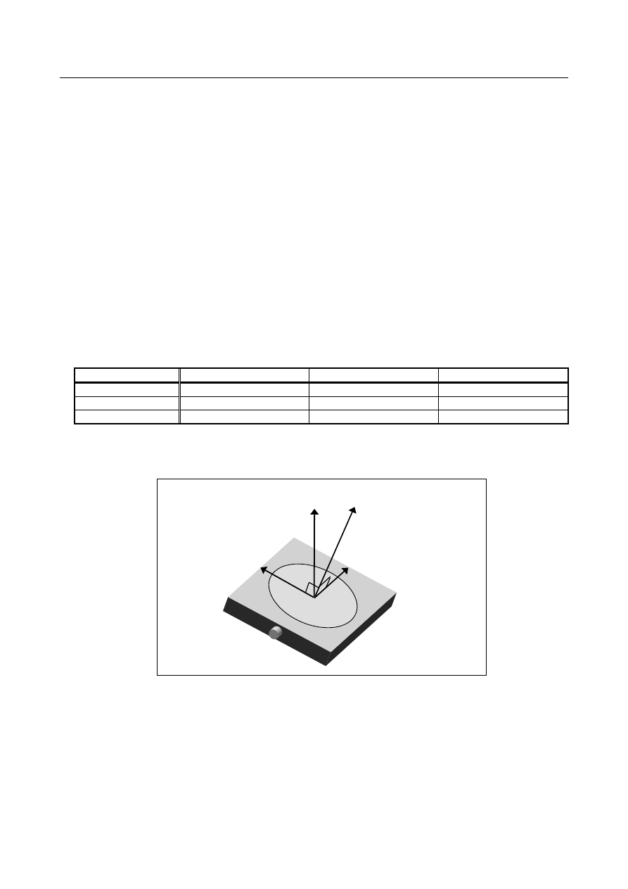
Table vertical direction: T
Table horizontal direction 2
(latitude direction): R2
Table horizontal direction 1
(longitude direction): R1
Normal axis direction: P
Fig. 3.8.5 (c) Latitude and longitude directions
-
Table horizontal direction feed in the tilted working plane indexing mode
If bit 0 (TWD) of parameter No. 12320 is set to 1, the feed direction of the table horizontal direction feed
in the tilted working plane indexing mode is defined as follows:
Table horizontal direction 1:
X direction in the feature coordinate system of the tilted working plane indexing
Table horizontal direction 2:
Y direction in the feature coordinate system of the tilted working plane indexing