FANUC Series 0i-MODEL F Plus. CONNECTION MANUAL (FUNCTION) - page 90
3. MANUAL OPERATION
B-64693EN-1/01
- 674 -
Table 3.8.2 (a) Tool axis direction
Parameter No. 19697
Tool axis right-angle direction 1
Tool axis right-angle direction 2
1
(The reference tool direction is +X.)
+Y direction
+Z direction
2
(The reference tool direction is +Y.)
+Z direction
+X direction
3
(The reference tool direction is +Z.)
+X direction
+Y direction
Fig. 3.9.2 (a) shows the tool axis right-angle directions that may be taken when the angles of all the
rotation axes for controlling the tool are 0 degree and when parameters Nos.19698 and 19699 are both set
to 0.
When the reference tool axis direction is inclined based on the settings of parameters Nos.19698 and
19699, the tool axis right-angle direction is also inclined as much.
As the rotation axes for controlling the tool rotate, the tool axis right-angle direction changes according to
the rotation axis angle.
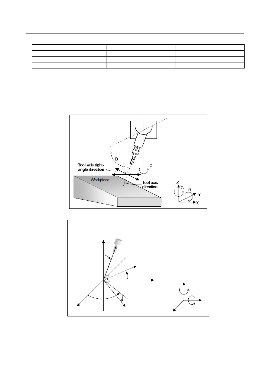
Fig. 3.8.2 (a) Tool axis direction
(Example)
When the tool rotation axes are B-axis and C-axis and the tool axis
direction is the Z-axis direction
C
B
Z
Y
X
Tool axis right-angle direction 2
Tool axis direction
B
C
Tool axis right-angle direction 1
Y
X
Z
B
C
Fig. 3.8.2 (b) Example of tool axis direction
-
Latitude and longitude directions
When bit 1 (FLL) of parameter No. 12320 is set to 1, the feed direction is defined as follows:
Let a vector perpendicular to a plane formed by the tool axis direction vector (
T
) and normal axis
direction vector (
P
) (parameter No. 12321) be the tool axis right-angle direction 1 (longitude direction)