FANUC Series 0i-MODEL F Plus. CONNECTION MANUAL (FUNCTION) - page 75
 

  Index      Manuals     FANUC Series 0i-MODEL F Plus. CONNECTION MANUAL (FUNCTION) B-64693EN-1/01


Search            copyright infringement  


Content      ..     73      74      75      76     ..


FANUC Series 0i-MODEL F Plus. CONNECTION MANUAL (FUNCTION) - page 75


2. PREPARATIONS FOR OPERATION


B-64693EN-1/01


- 554 - 


Signal address 


#7 

#6 

#5 

#4 

#3 

#2 

#1 

#0 

Fn001 


BAL 


AL 


2.5 

START LOCK / INTERLOCK 

These signals disable machine movement along axes. When any of these signals is activated during 
movement, tool movement along the affected axis (or axes) is decelerated, then stopped. 
 

Signal 

Start lock signal STLK<Gn007.1> 

  [Classification]  Input signal 
 

[Function] This signal disables movement along axes during automatic operation (memory operation, 

DNC operation, or MDI operation). 


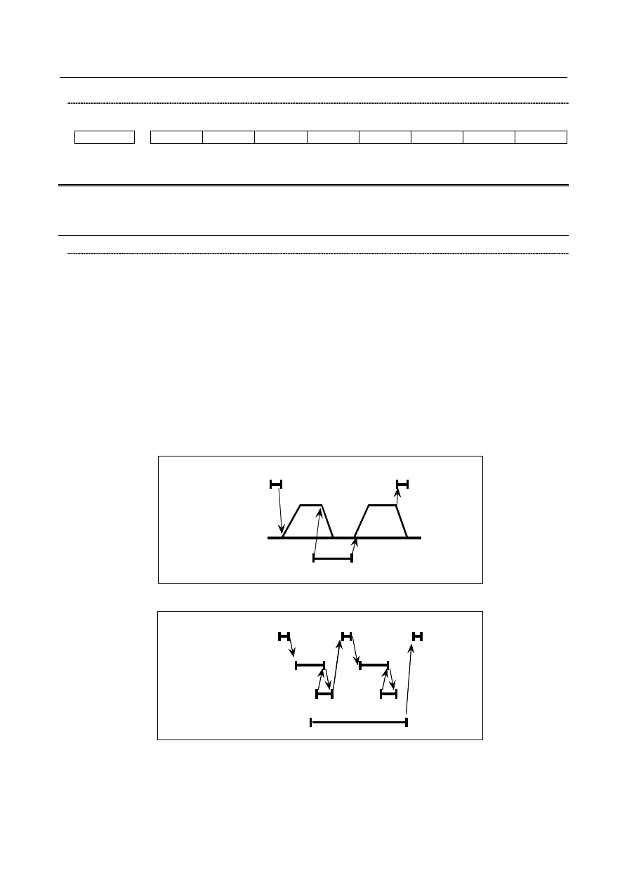
[Operation]  When the start lock signal STLK is set to “1”, a movement along an axis decelerates and 

stops. In this case, the automatic operation mode is maintained (with the cycle start lamp 
signal STL set to “1” and the feed hold lamp signal SPL set to “0”) while the movement 
is stopped. Therefore, when blocks containing only M, S, T, and B (second auxiliary 
functions) commands with no axis move commands are specified successively, the M, S, 
T, and B functions are executed one after another until a block specifying an axis move 
command is encountered. When an axis move command and M, S, T, and B functions are 
both specified, only the M, S, T, and B functions are sent, and a stop occurs in the 
automatic operation mode. Setting the start lock signal STLK to “0” restarts the operation. 
(Fig. 2.5 (a) and Fig. 2.5 (b)). 


STLK 

Command read 

Axis move 


Fig. 2.5 (a) Interlock when only axis move commands are specified 


Command read 

MF/SF/TF/BF 

FIN 

STLK 


Fig. 2.5 (b) Interlock when a block containing auxiliary functions only is specified 


B-64693EN-1/01


2. PREPARATIONS FOR OPERATION


- 555 - 

All axes interlock signal *IT<Gn008.0> 

  [Classification]  Input signal 
 

[Function]  This signal is used to inhibit the machine from moving, and is effective regardless of the 

selected mode. 


[Operation]  When the all axes interlock signal *IT is set to “0”, the axis movement is decelerated and 

stopped  regardless of the selected mode.  In this case, the automatic operation mode is 
maintained (with the cycle start lamp signal STL set to “1”and the feed hold lamp signal 
SPL set to “0”) while the movement is stopped. Therefore, when blocks containing only 
M, S, T, and B (second auxiliary functions) commands with no axis move commands are 
specified successively, the M, S, T, and B functions are executed one after another until a 
block specifying an axis move command is encountered. When an axis move command 
and M, S, T, and B functions are both specified, only the M, S, T, and B functions are 
sent, and a stop occurs in the automatic operation mode. Setting the axes interlock signal 
*IT to “1” restarts the operation. (Fig. 2.5 (c) and Fig. 2.5 (d)). 


Command read 

Axis move


*IT


Fig. 2.5 (c) Block containing axis move commands only (manual and automatic operation) 


Command read


MF/SF/TF/BF


FIN


*IT


Fig. 2.5 (d) Block containing auxiliary functions only (automatic operation) 


NOTE 

1  The overtravel distance of the motor after turning the all axes interlock signal *IT 

to “0” is represented by the following formula. 


Where 


Qmax=Fm

×

1/60

×

(A/1000+Tc/1000+Ts/1000) 

Qmax : Overtravel quantity (mm or inch) 
Fm    : Feedrate (mm/min or inch/min)   
Tc   

: Cutting time constant (ms) 

Ts   

: Servo time constant (Ts = 33ms normally) 

: Processing time of CNC 

  A = 50ms 


When acceleration/deceleration before read-ahead interpolation is used, the 
distance required for deceleration using look-ahead acceleration/deceleration 
before interpolation is added to the above formula. 

2  Interlock signal for each axis might become invalid by the function to use. Please 

refer to note at this paragraph end. 


2. PREPARATIONS FOR OPERATION


B-64693EN-1/01


- 556 - 

Interlock signal for each axis*IT1 to *IT8<Gn130> 

  [Classification]  Input signal 
 

[Function]  These signals disable feed along axes on an axis-by-axis basis. 

A separate interlock signal is provided for each controlled axis. The number at the end of 
each signal name denotes the number of the corresponding controlled axis. 
*IT x 
x    : 1 ..... Interlock for the first axis 

2 ..... Interlock for the second axis 
3 ..... Interlock for the third axis 
:      : 


[Operation]  a) 

In manual operation   


The movement of an interlocked axis is inhibited, but the other axes are movable. If 
an axis is interlocked during movement, it stops after being decelerated, and it starts 
moving again when it is released from interlock. 

b) 

In automatic operation (MEM, RMT, or MDI mode)   


If an axis is interlocked while its movement is being commanded (the move amount 
is not 0, inclusive of the tool offset), movement in all axes is prevented. 


If a moving axis is interlocked, all axes stop moving after being decelerated, and 
they start moving again when interlock is released. 


This function is also effective during dry run. 


NOTE 

  Interlock signal for each axis might become invalid by the function to 

use. Please refer to note at this paragraph end. 


Interlock signal for each axis direction 
(M series) +MIT1 to +MIT8<Gn132>,-MIT1 to -MIT8<Gn134> 
(T series) +MIT1<X004.2>,-MIT1<X004.3>,+MIT2<X004.4>,-MIT2<X004.5> 

  [Classification]  Input signal 
 

[Function]  An axis direction interlock can be applied for each axis. 


[Operation]  When an interlock signal for each axis direction is set to “1”, the CNC  applies an 

interlock to the specified axis direction only. However, when the interlock is done to the 
axis of movement instructing, the feed of all axes is prohibited regardless of axis 
direction. 
 

NOTE 

1  With the T series, if bit 4 (DAU) of parameter No. 3003 is set to 0, 

an axis direction interlock is applied only during manual operation. 
To apply axis direction interlock also during automatic operation, 
set bit 4 (DAU) of parameter No. 3003 to 1. 

2  With the T series, if bit 0 (GSC) of parameter No. 5009 is set to 1, 

the same signal addresses as the M series (<Gn132> and 
<Gn134>) can be set. When using these signals in a system using 
four or more paths, set bit 0 (GSC) of parameter No. 5009 to 1 to 
use signal addresses <Gn132> and <Gn134>. 

3  Interlock signal for each axis might become invalid by the function 

to use. Please refer to note at this paragraph end. 


B-64693EN-1/01


2. PREPARATIONS FOR OPERATION


- 557 - 

Block start interlock signal *BSL<Gn008.3> 

  [Classification]  Input signal 
 

[Function]  This signal disables the start of the next block during automatic operation 


[Operation]  While this signal is 0, the execution of the next block during automatic operation is not 

started. This signal does not affect a block that has already started, and that block is 
continuously executed until its end. This signal does not halt automatic operation. The 
command in the next block is ready for execution as a valid command, so execution 
restarts as soon as the signal is set to “1”. 


NOTE 

1  When blocks for cycle operation are internally created by a canned 

cycle and so on, only the first block is generally interlocked by this 
signal. The intermediate blocks are executed continuously even if 
this signal is set to “0”. 

2  This signal is invalid to the axis movement by the real-time custom 

macro sentence. 


Cutting block start interlock signal *CSL<Gn008.1> 

  [Classification]  Input signal 
 

[Function]  This signal disables the start of blocks specifying move commands other than positioning 

during automatic operation. 


[Operation]  While this signal is “0”, the execution of  blocks specifying movement other than 

positioning during automatic operation is not started. This signal does not affect a block 
that has already started, and that block is continuously executed until its end. This signal 
does not halt automatic operation. The command in the next block is ready for execution 
as a valid command, so execution restarts as soon as the signal is set to “1”. 


[Usage]  When the spindle has been specified, or when the spindle speed has been changed, this 

signal can be held 0 until a target spindle speed is achieved. Then, the next cutting block 
can be executed at the target spindle speed. 

NOTE 

1  This signal is effective for any blocks including blocks for cycle 

operation internally created by a canned cycle and so on. 

2  This signal is invalid to the axis movement by the real-time custom 

macro sentence. 


Signal address 


#7 

#6 

#5 

#4 

#3 

#2 

#1 

#0 

Gn007 


STLK 


Gn008 


*BSL 


*CSL 

*IT 


Gn130 


*IT8 

*IT7 

*IT6 

*IT5 

*IT4 

*IT3 

*IT2 

*IT1 


Gn132 


+MIT8 

+MIT7 

+MIT6 

+MIT5 

+MIT4 

+MIT3 

+MIT2 

+MIT1 


Gn134 


-MIT8 

-MIT7 

-MIT6 

-MIT5 

-MIT4 

-MIT3 

-MIT2 

-MIT1 


X004 


-MIT2 

+MIT2 

-MIT1 

+MIT1 


X013 


-MIT2

#2 

+MIT2

#2


-MIT1

#2


+MIT1

#2


X011 


-MIT2

#3


+MIT2

#3


-MIT1

#3


+MIT1

#3


2. PREPARATIONS FOR OPERATION


B-64693EN-1/01


- 558 - 


NOTE 


For the T series, the +MIT1, -MIT1, +MIT2, and -MIT2 signals are placed in X004 
(path 1), X013 (path 2), and X011 (path 3) shown above when bit 2 (XSG) of 
parameter No. 3008 is 0. When bit 2 (XSG) of parameter No. 3008 is 1, they are 
placed in the X addresses set by parameter No. 3019. (The bit positions do not 
change.) If bit 0 (GSC) of parameter No. 5009 is set to 1, an input signal can be 
input from the PMC side (Gn132 (- direction), Gn134 (+ direction)). In this case, 
the bit positions are the same as those in the M series. 


Parameter 


#7 

#6 

#5 

#4 

#3 

#2 

#1 

#0 

1002 


XIK 


[Input type]  Parameter input 


[Data type]  Bit path 


#4  XIK

  When bit 1 (LRP)  of parameter No. 1401 is set to 0, namely, when positioning is 

performed using non-linear type positioning, if an interlock is applied to the machine 
along one of axes in positioning, 
0: 

The machine stops moving along the axis for which the interlock is applied and 
continues to move along the other axes. 

1: 

The machine stops moving along all the axes. 


#7 

#6 

#5 

#4 

#3 

#2 

#1 

#0 

3003 


DAU 

DIT 

ITX 


ITL 


DIT 

ITX 


ITL 


[Input type]  Parameter input 


[Data type]  Bit path 


#0  ITL

  Interlock signal for all axes 

0: 

Enabled 

1: 

Disabled 


#2  ITX

  Interlock signals for each axis 

0: 

Enabled 

1: 

Disabled 


#3  DIT

  The interlock signal for each axis direction is: 

0: 

Valid. 

1: 

Invalid. 


#4  DAU

  When bit 3 (DIT) of parameter No. 3003 is set to 0, the interlock signal for each axis 

direction is: 
0: 

Valid only in manual operation, and invalid in automatic operation. 

1: 

Valid in either manual operation or automatic operation. 


B-64693EN-1/01


2. PREPARATIONS FOR OPERATION


- 559 - 


#7 

#6 

#5 

#4 

#3 

#2 

#1 

#0 

3004 


BCY 

BSL 


[Input type]  Parameter input 


[Data type]  Bit path 


#0  BSL

  The block start interlock signal *BSL and cutting block start interlock signal *CSL are: 

0: 

Disabled. 

1: 

Enabled. 


#1  BCY

  When more than one operation is performed by one block command such as a canned 

cycle, the block start interlock signal *BSL is: 
0: 

Checked only at the beginning of the first cycle. 

1: 

Checked at the beginning of every cycle. 


#7 

#6 

#5 

#4 

#3 

#2 

#1 

#0 

3008 


XSG 


[Input type]  Parameter input 


[Data type]  Bit path 


NOTE 


When this parameter is set, the power must be turned off before 
operation is continued. 


#2  XSG

  A signal assigned to an X address is: 

0: 

Fixed at the address. 

1: 

Able to be reassigned to an arbitrary X address. 


NOTE 


When this parameter is set to 1, set parameter No. 3013, No. 3014, 
No. 3012, and No. 3019. If parameter No. 3013 and No. 3014 are 
not set, the deceleration signal for reference position return 

*DEC

 is 

assigned to bit 0 of <Xn000>. If parameter No. 3012 and No. 3019 
are not set, the skip signal, the PMC axis control skip signal, the 
measurement position arrival signal, the interlock signal for each 
axis direction, and the tool compensation value write signal are 
assigned to <Xn000>. 


#7 

#6 

#5 

#4 

#3 

#2 

#1 

#0 

5009 


GSC 


[Input type]  Parameter input 


[Data type]  Bit path 


NOTE 


When this parameter is set, the power must be turned off before 
operation is continued. 


2. PREPARATIONS FOR OPERATION


B-64693EN-1/01


- 560 - 


#0  GSC

  When the function for direct input of offset value measured B is used, an offset write 

input signal is input from: 
0: 

Machine side 

1: 

PMC side 


NOTE 


When the interlock function for each axis direction is enabled (when 
bit 3 (DIT) of parameter No. 3003 is set to 0), switching can also be 
made between input from the machine side and input from PMC side 
for the interlock function for each axis direction. 


#7 

#6 

#5 

#4 

#3 

#2 

#1 

#0 

11600 


D3IT 


[Input type]  Parameter input 


[Data type]  Bit path 


#2  D3IT

  In the 3-dimensional coordinate system conversion mode, the valid interlock signals 

(interlock signal for each axis (*ITx) or interlock signal for each axis direction (MITx, 
PITx)) are: 
0: 

The signals for all of the target axes for 3-dimensional coordinate system 
conversion. 

1: 

The signals for axes along which a movement is made during 3-dimensional 
coordinate system conversion. 


B-64693EN-1/01


2. PREPARATIONS FOR OPERATION


- 561 - 

Note 

NOTE 

1  The interlock signal for each axis direction (T series) can be used regardless of 

whether the function for direct input of offset value measured B is provided or not. 

2  When an interlock is being applied to an axis, "I" appears on the left side of the 

axis address of the axis on the coordinate position display screen. 

3  There are the following functions to invalidate each interlock signal temporarily. 

(1) Interlock signal is invalid to the axes engaged in the synchronization 

establishment of axis synchronous control. 

(2) Interlock signal is invalid to slave axis in axis synchronous control. 
(3) In arbitrary angular axis control, when a movement is made along the angular 

axis only, interlocking the perpendicular axis does not interlock a movement 
along the perpendicular axis made by a movement along the angular axis. 

(4) Interlock signal is invalid to slave axis in EGB synchronization. 
(5) All axes interlock signal and interlock signal for each axis are invalid to a 

spindle during arbitrary speed threading. 

(6) Interlock signal of the slave axis is invalid to the superimposed control pulse 

added from the master axis during superimposed control. 

(7) In spindle orientation, all axes interlock signal and interlock signal for each 

axis are checked only when a block is started. A signal is ignored if input 
during the execution of the block. 

(8) Interlock signal is invalid to the axis control command of the real-time custom 

macro. 

(9) In polygon turning, interlock signal is invalid to the tool rotation axis while 

synchronous operation. 

(10) Interlock signals are invalid for PMC axis control. 
(11) Interlock signal is invalid to the synchronous slave axis of synchronous 

control. Interlock signal is invalid to the composite side of composite control. 

5  If interlock is applied to the oscillation axis during oscillation motion, the 

oscillation axis stops immediately. 

6  In synchronous control, interlock signals on the synchronous master side are 

effective for the synchronous slave axes. 
In composite control, interlock signals in the specified path are effective. 

7  The behavior of interlock signals in each axis or interlock signal for each axis 

direction during 3-dimensional coordinate system conversion mode follows the 
setting of bit 2 (D3IT) of parameter No.11600 and bit 5 (ITM) of parameter 
No.11223. For details, see the sections on "3-dimensional coordinate 
conversion". 


2.6 

MODE SELECTION 

Overview 

The mode selection signal is a code signal consisting of the three bits MD1, MD2, and MD4. 
The following five modes can be selected depending on the combination of these signals. 

Memory edit (EDIT) 

Memory operation (MEM) 

Manual data input (MDI) 

Manual handle/incremental feed (HANDLE/INC) 

Manual continuous feed (JOG) 


Content      ..     73      74      75      76     ..