FANUC Series 0i-MODEL F Plus. CONNECTION MANUAL (FUNCTION) - page 74
 

  Index      Manuals     FANUC Series 0i-MODEL F Plus. CONNECTION MANUAL (FUNCTION) B-64693EN-1/01


Search            copyright infringement  


Content      ..     72      73      74      75     ..


FANUC Series 0i-MODEL F Plus. CONNECTION MANUAL (FUNCTION) - page 74


2. PREPARATIONS FOR OPERATION


B-64693EN-1/01


- 546 - 


Signal address 


#7 

#6 

#5 

#4 

#3 

#2 

#1 

#0 

Gn060 


*TSB 


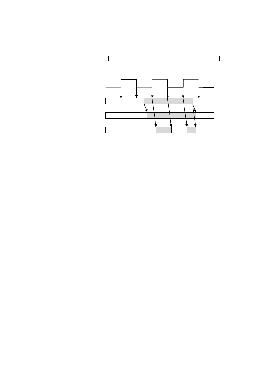
Timing chart 


Tailstock barrier 
select signal *TSB 

G22/G23 
 

Chuck barrier 
 

Tail stock barrier 
 

G23 

G22 

G23 

Invalid 

Valid 

Invalid 

Invalid 

Valid 

Invalid  Valid 

Invalid 


Limitation 

  - 

Correct setting of an entry-inhibition area 

If an entry-inhibition area is incorrectly set, it may not be possible to make the area effective. Avoid 
making the following settings: 

L < L1 or W < W1 in the chuck-shape settings. 

D2 < D3 in the tail stock-shape settings. 

A chuck setting overlapping that of the tail stock. 


When you use only the chuck or only the tail stock 

Setting of direction of entry-inhibition area for a chuck and of entry-inhibition area for a tail stock is 
decided by a big and small relation between CZ and TZ. Even when you use only the chuck or only the 
tail stock, please set a big and small relation between CZ and TZ appropriately. Please refer to "Setting of 
direction of chuck and of tail stock" for details.   
 
If you not use the entry-inhibition area for a chuck, please set 0 to L, L1, W and W1 of the chuck-shape 
settings. 
If you not use the entry-inhibition area for a tail stock, please set 0 to L, L1, L2, D, D1, D2 and D3 of the 
tail stock-shape settings. 
 

  - 

Retraction from the entry-inhibition area 

If the tool enters the entry-inhibition area and an alarm is issued, switch to manual mode, retract the tool 
manually, then reset the system to release the alarm. In manual mode, the tool can be moved only in the 
opposite direction to that in which the tool entered the area. 
The tool cannot be moved in the same direction (further into the area) as it was traveling when the tool 
entered the area. 
When the entry-inhibition areas for the chuck and tail stock are enabled, and the tool is already positioned 
within those areas, an alarm is issued when the tool moves. 
When the tool cannot be retracted, change the setting of the entry-inhibition areas, such that the tool is 
outside the areas, reset the system to release the alarm, then retract the tool. Finally, reinstall the original 
settings. 
 

B-64693EN-1/01


2. PREPARATIONS FOR OPERATION


- 547 - 

  - 

Coordinate system 

An entry-inhibition area is defined using the workpiece coordinate system. Note the following. 
<1>  When the workpiece coordinate system is shifted by means of a command or operation, the 

entry-inhibition area is also shifted by the same amount. 


Machine coordinate system 

Entry-inhibition 
area 

Old workpiece 
coordinate system 

Entry-inhibition 
area 

New workpiece 
coordinate system 


Fig. 2.3.11 (f) 


Use of the following commands and operations will shift the workpiece coordinate system. 
Commands: 
 

G54 to G59, G52, G50 (G92 in G code system B or C) 

Operations: 
 

Manual handle interrupt, change in offset relative to the workpiece reference point, change in 
tool offset (tool geometry compensation), operation with machine lock, manual operation with 
manual absolute signal off 

<2>  When the tool enters an entry-inhibition area during automatic operation, set the manual absolute 

signal, *ABSM <Gn006.2>, to 0 (on), then manually retract the tool from the area. If this signal is 
“1”, the distance the tool moves in manual operation is not counted in the tool coordinates in the 
workpiece coordinate system. This results in the state where the tool can never be retracted from the 
entry-inhibition area. 


Parameter 

  - 

Profile of a chuck 

1330 


Profile of a chuck 


[Input type]  Parameter input 


[Data type]  Byte path 

[Valid data range]  0 to 1 

Select a chuck figure. 
0 :  Chuck which holds a workpiece on the inner surface 
1 :  Chuck which holds a workpiece on the outer surface 
 

1331 


Dimensions of the claw of a chuck (L) 


[Input type]  Parameter input 


[Data type]  Real path 


[Unit of data]  mm, inch (input unit) 

[Min. unit of data]  Depend on the increment system of the applied axis 
[Valid data range]  0 or positive 9 digit of minimum unit of data (refer to the standard parameter setting table 

(B)) 
(When the increment system is IS-B, 0.0 to +999999.999) 
Set the length (L) of the claw of the chuck. 

2. PREPARATIONS FOR OPERATION


B-64693EN-1/01


- 548 - 

NOTE 


Whether to specify this parameter by using a diameter value or 
radius value depends on whether the corresponding axis is based 
on diameter specification or radius specification. 


1332 


Dimensions of the claw of a chuck (W) 


[Input type]  Parameter input 


[Data type]  Real path 


[Unit of data]  mm, inch (input unit) 

[Min. unit of data]  Depend on the increment system of the applied axis 
[Valid data range]  0 or positive 9 digit of minimum unit of data (refer to the standard parameter setting table 

(B)) 
(When the increment system is IS-B, 0.0 to +999999.999) 
Set the width (W) of the claw of the chuck. 
 

NOTE 


Specify this parameter by using a radius value at all times. 


1333 


Dimensions of the claw of a chuck (L1) 


[Input type]  Parameter input 


[Data type]  Real path 


[Unit of data]  mm, inch (input unit) 

[Min. unit of data]  Depend on the increment system of the applied axis 
[Valid data range]  0 or positive 9 digit of minimum unit of data (refer to the standard parameter setting table 

(B)) 
(When the increment system is IS-B, 0.0 to +999999.999) 
Set the length (L1) of the claw of the chuck. 
 

NOTE 


Whether to specify this parameter by using a diameter value or 
radius value depends on whether the corresponding axis is based 
on diameter specification or radius specification. 


1334 


Dimensions of the claw of a chuck (W1) 


[Input type]  Parameter input 


[Data type]  Real path 


[Unit of data]  mm, inch (input unit) 

[Min. unit of data]  Depend on the increment system of the applied axis 
[Valid data range]  0 or positive 9 digit of minimum unit of data (refer to the standard parameter setting table 

(B)) 
(When the increment system is IS-B, 0.0 to +999999.999) 
Set the width (W1) of the claw of the chuck. 
 

NOTE 


Specify this parameter by using a radius value at all times. 


B-64693EN-1/01


2. PREPARATIONS FOR OPERATION


- 549 - 

1335 


X coordinate of a chuck (CX) 


[Input type]  Parameter input 


[Data type]  Real path 


[Unit of data]  mm, inch (input unit) 

[Min. unit of data]  Depend on the increment system of the applied axis 
[Valid data range]  9 digit of minimum unit of data (refer to standard parameter setting table (A)) 

(When the increment system is IS-B, -999999.999 to +999999.999) 
Set the chuck position (X coordinate) in the workpiece coordinate system. 
 

NOTE 


Whether to specify this parameter by using a diameter value or 
radius value depends on whether the corresponding axis is based 
on diameter specification or radius specification.   


1336 


Z coordinate of a chuck (CZ) 


[Input type]  Parameter input 


[Data type]  Real path 


[Unit of data]  mm, inch (input unit) 

[Min. unit of data]  Depend on the increment system of the applied axis 
[Valid data range]  9 digit of minimum unit of data (refer to standard parameter setting table (A)) 

(When the increment system is IS-B, -999999.999 to +999999.999) 
Set the chuck position (Z coordinate) in the workpiece coordinate system. 
 

NOTE 

1  Whether to specify this parameter by using a diameter value or 

radius value depends on whether the corresponding axis is based 
on diameter specification or radius specification.   

2  The direction of the chuck and of the tail stock is decided by a big 

and small relation between this parameter and parameter No.1348 
(Z coordinate of a tail stock (TZ)). Even when you not use the 
chuck, please set to this parameter. 


  - 

Profile of a tail stock 

1341 


Length of a tail stock (L) 


[Input type]  Parameter input 


[Data type]  Real path 


[Unit of data]  mm, inch (input unit) 

[Min. unit of data]  Depend on the increment system of the applied axis 
[Valid data range]  0 or positive 9 digit of minimum unit of data (refer to the standard parameter setting table 

(B)) 
(When the increment system is IS-B, 0.0 to +999999.999) 
Set the length (L) of the tail stock. 
 

NOTE 


Whether to specify this parameter by using a diameter value or 
radius value depends on whether the corresponding axis is based 
on diameter specification or radius specification.   

2. PREPARATIONS FOR OPERATION


B-64693EN-1/01


- 550 - 


1342 


Diameter of a tail stock (D) 


[Input type]  Parameter input 


[Data type]  Real path 


[Unit of data]  mm, inch (input unit) 

[Min. unit of data]  Depend on the increment system of the applied axis 
[Valid data range]  0 or positive 9 digit of minimum unit of data (refer to the standard parameter setting table 

(B)) 
(When the increment system is IS-B, 0.0 to +999999.999) 
Set the diameter (D) of the tail stock. 
 

NOTE 


Specify this parameter by using a diameter value at all times. 


1343 


Length of a tail stock (L1) 


[Input type]  Parameter input 


[Data type]  Real path 


[Unit of data]  mm, inch (input unit) 

[Min. unit of data]  Depend on the increment system of the applied axis 
[Valid data range]  0 or positive 9 digit of minimum unit of data (refer to the standard parameter setting table 

(B)) 
(When the increment system is IS-B, 0.0 to +999999.999) 
Set the length (L1) of the tail stock. 
 

NOTE 


Whether to specify this parameter by using a diameter value or 
radius value depends on whether the corresponding axis is based 
on diameter specification or radius specification.   


1344 


Diameter of a tail stock (D1) 


[Input type]  Parameter input 


[Data type]  Real path 


[Unit of data]  mm, inch (input unit) 

[Min. unit of data]  Depend on the increment system of the applied axis 
[Valid data range]  0 or positive 9 digit of minimum unit of data (refer to the standard parameter setting table 

(B)) 
(When the increment system is IS-B, 0.0 to +999999.999) 
Set the diameter (D1) of the tail stock. 
 

NOTE 


Specify this parameter by using a diameter value at all times. 


1345 


Length of a tail stock (L2) 


[Input type]  Parameter input 


[Data type]  Real path 


[Unit of data]  mm, inch (input unit) 

B-64693EN-1/01


2. PREPARATIONS FOR OPERATION


- 551 - 

[Min. unit of data]  Depend on the increment system of the applied axis 
[Valid data range]  0 or positive 9 digit of minimum unit of data (refer to the standard parameter setting table 

(B)) 
(When the increment system is IS-B, 0.0 to +999999.999) 
Set the length (L2) of the tail stock. 
 

NOTE 


Whether to specify this parameter by using a diameter value or 
radius value depends on whether the corresponding axis is based 
on diameter specification or radius specification.   


1346 


Diameter of a tail stock (D2) 


[Input type]  Parameter input 


[Data type]  Real path 


[Unit of data]  mm, inch (input unit) 

[Min. unit of data]  Depend on the increment system of the applied axis 
[Valid data range]  0 or positive 9 digit of minimum unit of data (refer to the standard parameter setting table 

(B)) 
(When the increment system is IS-B, 0.0 to +999999.999) 
Set the diameter (D2) of the tail stock. 
 

NOTE 


Specify this parameter by using a diameter value at all times. 


1347 


Diameter of a tail stock (D3) 


[Input type]  Parameter input 


[Data type]  Real path 


[Unit of data]  mm, inch (input unit) 

[Min. unit of data]  Depend on the increment system of the applied axis 
[Valid data range]  0 or positive 9 digit of minimum unit of data (refer to the standard parameter setting table 

(B)) 
(When the increment system is IS-B, 0.0 to +999999.999) 
Set the diameter (D3) of the tail stock. 
 

NOTE 


Specify this parameter by using a diameter value at all times. 


1348 


Z coordinate of a tail stock (TZ) 


[Input type]  Parameter input 


[Data type]  Real path 


[Unit of data]  mm, inch (input unit) 

[Min. unit of data]  Depend on the increment system of the applied axis 
[Valid data range]  9 digit of minimum unit of data (refer to standard parameter setting table (A)) 

(When the increment system is IS-B, -999999.999 to +999999.999) 
Set the tail stock position (Z coordinate) in the workpiece coordinate system. 
 

2. PREPARATIONS FOR OPERATION


B-64693EN-1/01


- 552 - 

NOTE 

1  Whether to specify this parameter by using a diameter value or 

radius value depends on whether the corresponding axis is based 
on diameter specification or radius specification. 

2  The direction of the chuck and of the tail stock is decided by a big 

and small relation between this parameter and parameter No.1336 
(Z coordinate of a chuck (CZ)). Even when you not use the tail 
stock, please set to this parameter. 


#7 

#6 

#5 

#4 

#3 

#2 

#1 

#0 

1370 


CTA 


[Input type]  Parameter input 


[Data type]  Bit path 


NOTE 


When this parameter is set, the power must be turned off before 
operation is continued. 


#0  CTA

  The overtravel alarm of Chuck and Tail Stock Barrier is, 

0: 

Conventional specification. 

(Alarm OT0502, OT0503) 

1: 

New specification. 


(Alarm OT0520, OT0521) 


#7 

#6 

#5 

#4 

#3 

#2 

#1 

#0 

3402 


G23 


[Input type]  Parameter input 


[Data type]  Bit path 


#7  G23

  When the power is turned on 

0: 

G22 mode (stored stroke check on) 

1: 

G23 mode (stored stroke check off) 


Alarm and message 

Number 

Message 

Description 

OT0502 

+ OVERTRAVEL ( SOFT 2 ) 

Exceeded the positive side stored stroke limit 2. Or, in the 
chuck tail stock barrier, an entry to the entry-inhibition area 
was made during movement in the positive direction. 

OT0503 

- OVERTRAVEL ( SOFT 2 ) 

Exceeded the negative side stored stroke limit 2. Or, in the 
chuck tail stock barrier, an entry to the entry-inhibition area 
was made during movement in the negative direction. 

OT0520 

+ OVERTRAVEL (CHUCK TAIL 
BARRIER) 

In the chuck tail stock barrier, an entry to the entry-inhibition 
area was made during movement in the positive direction. 

OT0521 

- OVERTRAVEL (CHUCK TAIL 
BARRIER) 

In the chuck tail stock barrier, an entry to the entry-inhibition 
area was made during movement in the negative direction. 


B-64693EN-1/01


2. PREPARATIONS FOR OPERATION


- 553 - 

Warning 

  WARNING 

1  If an alarm is issued, the tool stops before it enters the entry-inhibition area when 

bit 7 (BFA) of parameter No. 1300 is set to 1. 


When bit 7 (BFA) of parameter No. 1300 is set to 0, an actual stop position can 
be in the entry-inhibition area beyond the specified profile because the CNC and 
machine system stop with some delay in time. For this reason, for safety, set 
profile data a little larger than the actual profile. The extra distance, L, required for 
this purpose is calculated from a rapid traverse rate as follows: 
L = (rapid-traverse-rate) 

×

 1/7500 

For example, when a rapid traverse rate of 15 m/min is used, set profile data 2 
mm larger than the actual profile. 
The profile of a chuck or tail stock can also be set using parameters Nos. 1330 to 
1348. 


Reference item 

Manual name 

Item name 

OPERATOR’S MANUAL (B-64694EN) 

Check/tail stock barrier 


2.4 

ALARM SIGNALS 

When an alarm is triggered in the CNC, the alarm is displayed on the screen, and the alarm signal is set to 
“1”. 
If the voltage level of the memory backup battery falls to below a specified level while the CNC is turned 
off, the battery alarm signal is set to “1”. 
 

Signal 

Alarm signal AL<Fn001.0> 

  [Classification]  Output signal 
 

[Function]  The alarm signal reports that the CNC is in an alarm state. 

The following are the alarms that may be issued: 
(a)  TH alarm 
(b)  TV alarm 
(c)  P/S alarm 
(d)  Overtravel alarm 
(e)  Overheat alarm 
(f)  Servo alarm 


[Output cond.]  The alarm signal is set to “1” when: 

The CNC is placed in the alarm state. 

The alarm signal is set to “0” when: 
-   

The alarm has been released by resetting the CNC. 


Battery alarm signal BAL<Fn001.2> 

  [Classification]  Output signal 
 

[Function]  The battery alarm signal indicates that the voltage of the battery for the memory has 

fallen to below a specified level while the CNC is off. In general, this signal is used to 
turn on an LED to notify the operator. 


[Output cond.]  The signal is set to “1” when: 

The battery voltage has fallen to below the specified level. 

The signal is set to “0” when: 

The battery voltage has risen to the specified level or higher. 


Content      ..     72      73      74      75     ..