FANUC Series 0i-MODEL F Plus. CONNECTION MANUAL (FUNCTION) - page 68
 

  Index      Manuals     FANUC Series 0i-MODEL F Plus. CONNECTION MANUAL (FUNCTION) B-64693EN-1/01


Search            copyright infringement  


Content      ..     66      67      68      69     ..


FANUC Series 0i-MODEL F Plus. CONNECTION MANUAL (FUNCTION) - page 68


1. AXIS CONTROL


B-64693EN-1/01


- 498 - 

Table 1.17 (b) Setting example 1 

Parameter 

Setting value 


Parameter 

Setting value 

No.14270 

-3000.0 


No.14280 

100 

No.14271 

-2500.0 


No.14281 

150 

No.14272 

-2000.0 


No.14282 

100 

No.14273 

-800.0 


No.14283 

100 

No.14274 

-500.0 


No.14284 

50 

No.14275 

500.0 


No.14285 

50 

No.14276 

800.0 


No.14286 

100 

No.14277 

2000.0 


No.14287 

100 

No.14278 

2500.0 


No.14288 

150 

No.14279 

3000.0 


No.14289 

100 


Fig. 1.17 (a)  Compensation coefficient (example 1) 

 
Example 2) 
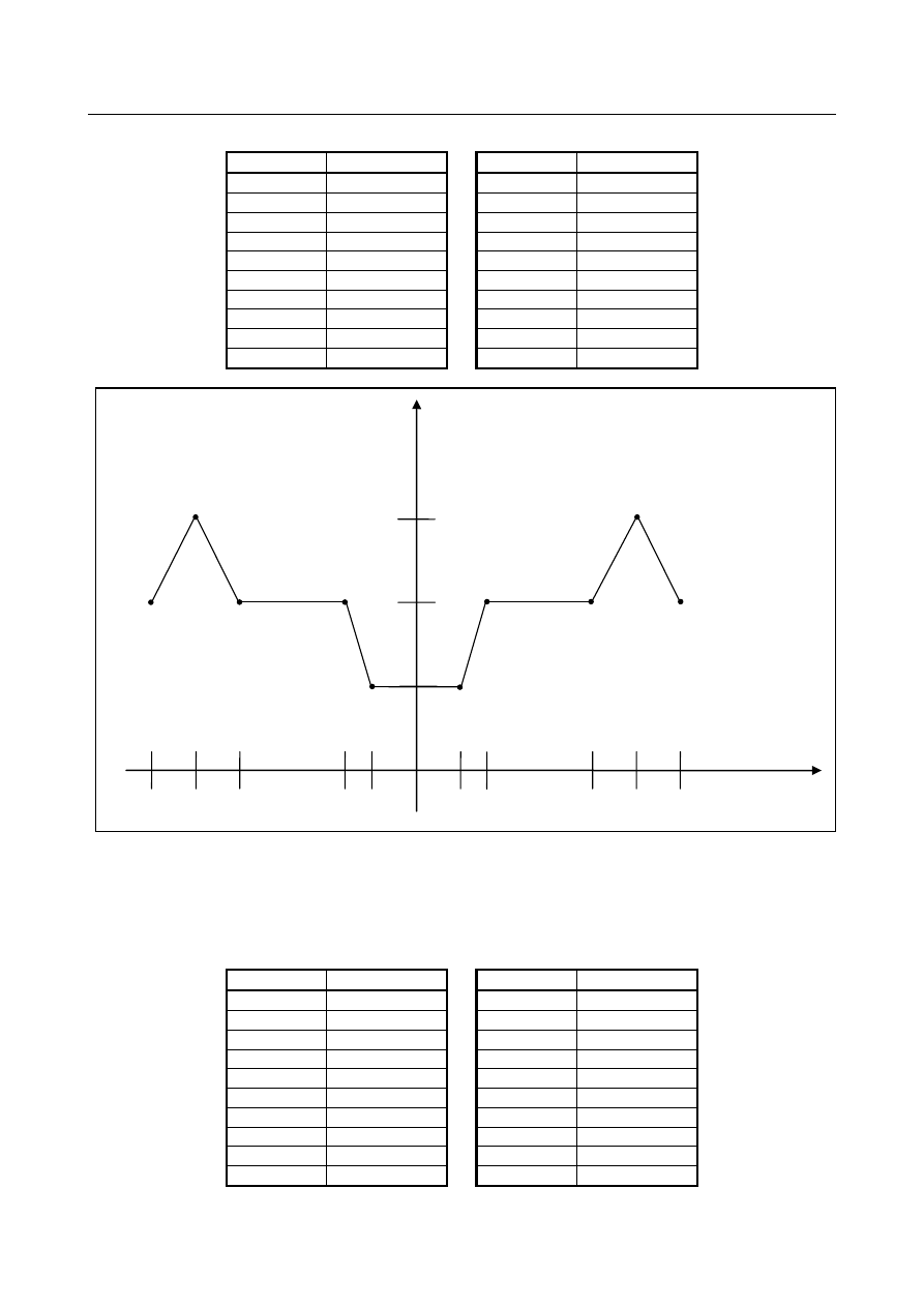
When setting the parameter in Table 1.17 (c) below, compensation coefficients of the compensation axis 
are as shown in Fig. 1.17 (b) . 
 

Table 1.17 (c) Setting example 2 

Parameter 

Setting value 


Parameter 

Setting value 

No.14270 

-5.0 


No.14280 

50 

No.14271 

1000.0 


No.14281 

150 

No.14272 

0.0 


No.14282 

No.14273 

0.0 


No.14283 

No.14274 

0.0 


No.14284 

No.14275 

0.0 


No.14285 

No.14276 

0.0 


No.14286 

No.14277 

0.0 


No.14287 

No.14278 

0.0 


No.14288 

No.14279 

0.0 


No.14289 


Compensation coefficient (K) 

150 

100 

50 

-3000.0 

-2500.0 

-2000.0 

-800.0 

-500.0 

500.0 

800.0 

2000.0 

2500.0 

3000.0 

Machine   

coordinate of   

moving axis 

B-64693EN-1/01


1. AXIS CONTROL


- 499 - 


Fig. 1.17 (b)  Compensation coefficient (example 2) 


NOTE 

1  This function is enabled after reference position return of moving axis and 

compensation axis are completed. 

2  Set the parameter No.14270 to No.14279 setting so that the set value of the 

small parameter number becomes smaller. (No.14270 setting value < No.14271 
setting value < … < No.14279 setting value) When the magnitude relation of the 
setting value is not established, subsequent parameter setting becomes invalid. 
In the case of Table 1.17 (c), since the setting value of No.14271 is larger than 
the setting value of No.14272, parameter setting after No.14272 is invalid. 

3  This function is invalid if the machine coordinate value of moving axis is out of 

the range of parameter No.14270 to No.14279 set value. 


Limitation 

Moving axis and compensation axis must be assigned to be the same path. 

When the axis used this function, the following function cannot be used. 
  - Cs contouring control 
  - Spindle control with servo motor 
  - Temporary absolute coordinate setting 
 

Parameter 

2069 


Velocity feedforward coefficient (VFFLT) 


[Input type]  Parameter input 


[Data type]  Word axis 


[Unit of data]  % 

  [Recommendation] 50 to 200 


2145 


Velocity feedforward coefficient for cutting feed 


[Input type]  Parameter input 

-5.0 

1000.0 

50 

150 

Machine   

coordinate of   

moving axis 
 

Compensation coefficient (K) 

1. AXIS CONTROL


B-64693EN-1/01


- 500 - 


[Data type]  Word axis 


[Unit of data]  % 

  [Recommendation] 50 to 200 


11821 


Controlled axis number of moving axis 


[Input type]  Parameter input 


[Data type]  Byte axis 

[Valid data range]  0, 1 to 24 

Specify controlled axis number. 
When 0 is set, this function is invalid. 
 

NOTE 

1  When this parameter is set, the power must be turned off before 

operation is continued. 

2  Set this parameter on compensation axis. 


14270 


Machine coordinate 1 of moving axis 


14271 


Machine coordinate 2 of moving axis 


14272 


Machine coordinate 3 of moving axis 


14273 


Machine coordinate 4 of moving axis 


14274 


Machine coordinate 5 of moving axis 


14275 


Machine coordinate 6 of moving axis 


14276 


Machine coordinate 7 of moving axis 


14277 


Machine coordinate 8 of moving axis 


14278 


Machine coordinate 9 of moving axis 


14279 


Machine coordinate 10 of moving axis 


[Input type]  Parameter input 


[Data type]  Real axis 


[Unit of data]  mm, inch, deg (machine unit) 

[Min. unit of data]  Depend on the increment system of the applied axis 
  [Valid data range] 9digit of minimum unit of data (refer to standard parameter setting table (A)) 

(When the increment system is IS-B, -999999.999 to +999999.999) 
Specify the machine coordinate value of the moving axis. 
 

NOTE 

1  When this parameter is set, the power must be turned off before 

operation is continued. 

2  Set this parameter on compensation axis. 


14280 


Compensation coefficient 1 of compensation axis 


B-64693EN-1/01


1. AXIS CONTROL


- 501 - 

14281 


Compensation coefficient 2 of compensation axis 


14282 


Compensation coefficient 3 of compensation axis 


14283 


Compensation coefficient 4 of compensation axis 


14284 


Compensation coefficient 5 of compensation axis 


14285 


Compensation coefficient 6 of compensation axis 


14286 


Compensation coefficient 7 of compensation axis 


14287 


Compensation coefficient 8 of compensation axis 


14288 


Compensation coefficient 9 of compensation axis 


14289 


Compensation coefficient 10 of compensation axis 


[Input type]  Parameter input 


[Data type]  2-word axis 


[Unit of data]  % 

[Valid data range] 1 to 1000 

Specify the compensation coefficient of compensation axis. 
 

NOTE 

1  When this parameter is set, the power must be turned off before 

operation is continued. 

2  Set this parameter on compensation axis. 
3  When a value outside the data range is set, 100 is assumed to be 

set. 


2. PREPARATIONS FOR OPERATION


B-64693EN-1/01


- 502 - 

PREPARATIONS FOR OPERATION 

2.1 

EMERGENCY STOP 

Overview 

By pressing the emergency stop button on the machine operation panel, you can immediately stop the 
movement of the machine in case of emergency. 


Fig. 2.1 (a) EMERGENCY STOP BUTTON 

 
This button is locked when it is pressed. Although it varies with the machine tool builder, the button can 
usually be unlocked by twisting it. 
 

Signal 

Emergency stop (input) 

*ESP<X008.4> (for the first machine group), <X008.0> (for the second machine 
group), <X008.1> (for the third machine group), <Gn008.4> 

  [Classification]  Input signal 
 

[Function]  Immediately stop the movement of the machine in case of emergency. 


[Operation]  When the emergency stop signal *ESP turns to “0”, the emergency stop is applied to the 

machine and the CNC is reset. In general, this signal is controlled by the B contacts of a 
pushbutton switch. The emergency stop signal turns the servo ready signal SA to “0”. 
In this CNC, it is the basic specification that overtravel detection is performed  by the 
stored stroke check function. A limit switch for normal overtravel detection is not needed.   
To prevent the machine from moving beyond the software limit through servo feedback 
error, always install a stroke end limit switch (shown in Fig. 2.1 (b) as follows). 


Emergency stop limit switch


+X


-X


+Y


-Y


+Z


-Z


+4


-4


Emergency stop temporary 


EMG


SK


Spark killer


Relay power 
supply


Fig. 2.1 (b) Connection of emergency stop limit switch 


B-64693EN-1/01


2. PREPARATIONS FOR OPERATION


- 503 - 

The distance from the position where the dynamic brake is applied to that where the tool stops moving is 
given in the "

FANUC AC SERVO MOTOR α

i

-

B/α

i

 series DESCRIPTIONS (B-65262EN)." 


  WARNING 


About the software limit setting point and operating point of limit switch for 
emergency stop   


The stop point by the software limit goes beyond the setting point by as much as 
the following distance. 


The actual stopping point may exceed the position set by parameters Nos.1320 
and 1321 by as much as R/7500 (mm).   
R/7,500 (mm) 


R: Rapid traverse rate (mm/min)   


Set the limit switch for emergency stop including the allowance for the above 
value. 


The machine stops in this range. 

Set the moving point of the emergency stop 
limit switch within this range. 

Software limit setting point 

Stroke end direction 

7,500 


Signal address 


#7 

#6 

#5 

#4 

#3 

#2 

#1 

#0 

X008 


*ESP 


(*ESP) 

(*ESP) 


Gn008 


*ESP 


Reference item 

Manual name 

Item name 

FANUC AC SERVO MOTOR 

α

i

 series DESCRIPTIONS 

(B-65262EN) 

Servo motor selection 


2.2 

CNC READY SIGNALS 

Overview 

When the CNC is turned on and becomes ready for operation, the CNC ready signal is set to 1. 
 

Signal 

CNC Ready Signal MA<Fn001.7> 

  [Classification]  Output signal 
 

[Function]  The CNC ready signal indicates that the CNC is ready. 


[Output cond.]  When the CNC is turned on and becomes ready for operation, the signal is set to “1”. 

Normally, it takes several seconds to establish this state after the power is turned on. If a 
system alarm is issued, the signal is set to “0”. The signal remains set to “1”, however, 
when an emergency stop or a similar operation is performed. 

2. PREPARATIONS FOR OPERATION


B-64693EN-1/01


- 504 - 

Servo Ready Signal SA<Fn000.6> 

  [Classification]  Output signal 
 

[Function]  Signal SA turns to “1” when the servo system is ready to operate. On the machine side, 

for an axis that is to be braked, release the brake when this signal is “1” and apply the 
brake when this signal is “0”.   
Time chart of this signal is as Fig. 2.2 (a). 


Power off 


Ready signal (MA) 


Power on 


60 to 100 


Servo alarm 


Servo alarm 


(Overload) 


1 to 2 seconds 


About 1 second 


Reset 


Reset 


Emergency 

stop


Servo ready 

signal (SA) 


Brake on 


Fig. 2.2 (a)  Time chart for servo ready signal 


Signal address 


#7 

#6 

#5 

#4 

#3 

#2 

#1 

#0 

Fn000 


SA 


Fn001 


MA 


2.3 

OVERTRAVEL CHECK 

2.3.1 

Overtravel Signals 

Overview 

When the tool tries to move beyond the stroke end set by the machine tool limit switch, the tool 
decelerates and stops as a result of tripping the limit switch, and an OVER TRAVEL is displayed. 
 

Signal 

Overtravel signals *+L1 to *+L8<Gn114>, *-L1 to *-L8<Gn116> 

  [Classification]  Input signal 
 

  [Function]  Indicates that the control axis has reached its stroke limit. There are individual signals for 

each direction in every control axis.   
The +/- in the signal name indicates the direction and the number at the end indicates the 
control axis number.   
+Lx 

B-64693EN-1/01


2. PREPARATIONS FOR OPERATION


- 505 - 

x  : 1 : No. 1 axis is at stroke limit. 

2 : No. 2 axis is at stroke limit. 
3 : No. 3 axis is at stroke limit. 


8 : No. 8 axis is at stroke limit. 
+ : Limit reached in + direction. 
- : Limit reached in - direction. 


[Operation]  When it is “0”, the control unit operates as given below. 

In automatic operation, if even one axis overtravel signal turns to “0”, all axes are 
decelerated to stop, an alarm is given and operation is halted. 

In manual operation, decelerates and stops movement of the axis "0" in the direction 
of "0" only, and the axis can be moved in the opposite direction. 

Once the axis overtravel signal has turned to “0”, the axis and direction is registered. 
Even if the signal returns to “1”, it is not possible to move that axis in that direction 
until the alarm is cleared. 

 
The following shows the deceleration distance at overtravel. 
(i)  Exponential acceleration/deceleration 


*+L

α

 limit switch 

Servo system delay 

t

2


t

1


Command pulse deceleration 

T

S


L=V(t

1

+t

2

+T+T

S

)

×

1/60000 [mm or inch] 


L :  Deceleration distance 
V :  Feedrate [mm/min or inch/min] 
t

1

 : 

Limit switch signal delay time (from limit switch operation to *+Lα signal turn 
off [msec]) 

t

2

 :  Receiver delay time 30msec 

T :  Acceleration/deceleration time [msec] 
T

S

 :  Servo system delay [msec] 

 
(ii)  Linear acceleration/deceleration 


L=V(t

1

+t

2

+T/2+T

S

)

×

1/60000 [mm or inch] 


Content      ..     66      67      68      69     ..