FANUC Series 0i-MODEL F Plus. CONNECTION MANUAL (FUNCTION) - page 66
 

  Index      Manuals     FANUC Series 0i-MODEL F Plus. CONNECTION MANUAL (FUNCTION) B-64693EN-1/01


Search            copyright infringement  


Content      ..     64      65      66      67     ..


FANUC Series 0i-MODEL F Plus. CONNECTION MANUAL (FUNCTION) - page 66


1. AXIS CONTROL


B-64693EN-1/01


- 482 - 

NOTE 

1  If an oscillation operation due to the oscillation start signal CHPST 

has been cancelled by an operation or command that causes it to 
stop, return the signal CHPST to "0" and then set it "1" again. 

2  This signal is not enabled until the completion of manual reference 

position return. 

3  The M codes which are used to set the oscillation start signal 

CHPST <Gn051.6> to "1" or "0" should be specified as M code 
preventing buffering (parameter Nos. 3411 to 3432). 


Oscillation hold signal *CHLD <Gn051.7> 


[Classification]  Input signal 


[Function]  Suspends oscillation.


[Operation] Once this signal has been set to "0", the tool is moved from the current position to point R, 

thus oscillation is suspended. Setting this signal to "1" while oscillation is suspended 
causes oscillation to be restarted.


Oscillation feedrate override signals *CHP1 to *CHP8 <Gn051.0 to 3> 


[Classification]  Input signal 


[Function]  Overrides the oscillation feedrate.


[Operation]  The actual base feedrate during oscillation becomes the specified base feedrate multiplied 

by the override value specified with this  signal.  The change amount by  the override  is 
affected the parameter No.25653 (Acceleration rate of starting or cancellation oscillation 
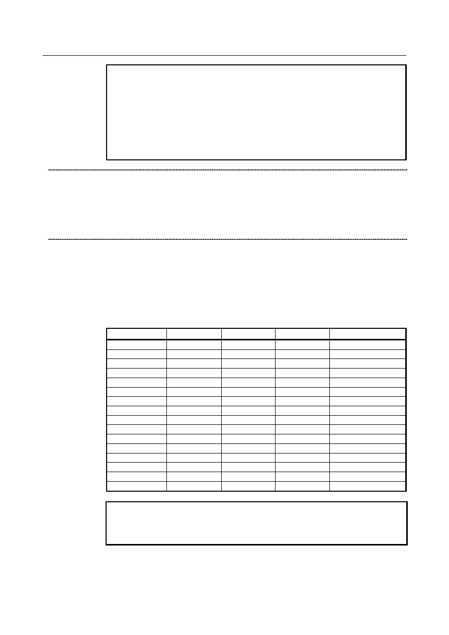
motion).  The following table lists the correspondence between the signal states and the 
override value:


*CHP8 

*CHP4 

*CHP2 

*CHP1 

Override value 

150% 

140% 

130% 

120% 

110% 

100% 

90% 

80% 

70% 

60% 

50% 

40% 

30% 

20% 

10% 

0% 


NOTE 


According to the range of oscillation motion and the oscillation base 
federate (Parameter No.8374), shock might occur when override is 
changed.   


B-64693EN-1/01


1. AXIS CONTROL


- 483 - 

Superimposed ahead signal OVLN <Gn531.4> 


[Classification]  Input signal 


[Function]  Start superimposed ahead mode.


[Operation]  When this signal is "1", the control device operates as follows. 

The corresponding path enters the superimposed ahead state. 

To switch superimposed ahead signal to "1" or "0", it is necessary to stop all axes (except 
for PMC axis) of path where this signal is switched. When axis moves, alarm DS0071 is 
issued. 
 

Oscillation-in-progress signal CHPMD <Fn039.2> 


[Classification]  Output signal 


[Function]  Notify the state of oscillation


[Operation]  This signal is set to "1" in the following cases: 

Oscillation start signal CHPST is changed from "0" to "1"


to start oscillation. 

Oscillation is started by G81.1 command. 

This signal is set to "0" in the following cases: 

Oscillation start signal CHPST is changed from "1" to "0" to stop oscillation. 

Oscillation is terminated by a reset.


Oscillation is cancelled by G80 command. 

Oscillation is terminated when an alarm is issued. 

Oscillation is terminated by emergency stop. 


Oscillation cycle signal CHPCYL <Fn039.3> 


[Classification]  Output signal 


[Function]  Notify the state of an oscillation cycle being performed between the upper and lower dead 

points.


[Operation]  This signal is set to "1" in the following case: 

Oscillation cycle is started and sign curve federate control is used between the upper 
and lower dead points. 

This signal is set to "0" in the following cases: 

Once oscillation has been stopped 

When the tool is stopped at the upper or lower dead point 

Oscillation hold signal *CHLD is set to "0" 


Superimposed ahead under way signal OVLNS <Fn545.1> 


[Classification]  Output signal 


[Function]  Indicates that superimposed ahead mode is executing.


[Operation]  The signal becomes "1" when: 

The corresponding path is executing superimposed ahead mode. 

The signal becomes "0" when: 

The corresponding path is not executing superimposed ahead mode. 


Signal address 


#7 

#6 

#5 

#4 

#3 

#2 

#1 

#0 

Gn051 


*CHLD 

CHPST 


*CHP8 

*CHP4 

*CHP2 

*CHP1 


Gn531 


OVLN 


Fn039 


CHPCYL 

CHPMD 


Fn545 


OVLNS 


1. AXIS CONTROL


B-64693EN-1/01


- 484 - 

Parameter 


#7 

#6 

#5 

#4 

#3 

#2 

#1 

#0 

8360 


CHF 


CVC 


ROV 


[Input type]  Setting input 


[Data type]  Bit path 


  #0  ROV

  As rapid traverse override for a section from the oscillation start point to point R: 

0: 

Oscillation override is used. 

1: 

Rapid traverse override is used. 


  #2  CVC

  The feedrate along the oscillation axis is changed: 

0: 

At the upper or lower dead point immediately after the feedrate change command is 
issued. 

1: 

At the upper dead point immediately after the feedrate change command is issued. 


  #7  CHF

  On the oscillation screen, the oscillation base feedrate: 

0: 

Can be set. 

1: 

Cannot be set. 


8370 


Oscillation axis 


[Input type]  Parameter input 


[Data type]  Byte path 

[Valid data range]  1 to Number of controlled axes 

This parameter sets which servo axis the oscillation axis corresponds to.


8371 


Oscillation reference point (point R) 


[Input type]  Parameter input 


[Data type]  Real path 


[Unit of data]  mm, inch, deg (input unit) 

[Min. unit of data]  Depend on the increment system of the oscillation axis 
[Valid data range]  9 digits of minimum unit of data (refer to standard parameter setting table (A)) 

(When the increment system is IS-B, -999999.999 to +999999.999) 
The data set in this parameter is absolute coordinates. 


8372 


Oscillation upper dead point 


[Input type]  Parameter input 


[Data type]  Real path 


[Unit of data]  mm, inch, deg (input unit) 

[Min. unit of data]  Depend on the increment system of the oscillation axis 
[Valid data range]  9 digits of minimum unit of data (refer to standard parameter setting table (A)) 

(When the increment system is IS-B, -999999.999 to +999999.999) 
The data set in this parameter is absolute coordinates. 


8373 


Oscillation lower dead point 


[Input type]  Parameter input 


[Data type]  Real path 


[Unit of data]  mm, inch, deg (input unit) 

[Min. unit of data]  Depend on the increment system of the oscillation axis 

B-64693EN-1/01


1. AXIS CONTROL


- 485 - 

[Valid data range]  9 digits of minimum unit of data (refer to standard parameter setting table (A)) 

(When the increment system is IS-B, -999999.999 to +999999.999) 
The data set in this parameter is absolute coordinates. 


8374 


Oscillation base feedrate 


[Input type]  Parameter input 


[Data type]  Real path 


[Unit of data]  mm/min, inch/min, deg/min (input unit) 

[Min. unit of data]  Depend on the increment system of the oscillation axis 
[Valid data range]  Refer to standard parameter setting table (C). 

(When the increment system is IS-B, 0.0 to +999000.0) 
This parameter sets the oscillation feedrate. 


8375 


Maximum oscillation feedrate 


[Input type]  Parameter input 


[Data type]  Real axis 


[Unit of data]  mm/min, inch/min, deg/min (machine unit) 

[Min. unit of data]  Depend on the increment system of the applied axis 
[Valid data range]  Refer to standard parameter setting table (C). 

(When the increment system is IS-B, 0.0 to +999000.0) 
The oscillation feedrate is clamped at this parameter setting. The maximum feedrate must 
be set for the oscillation axis. If this parameter is set to 0, no movement is made for 
oscillation. 


NOTE 


Please set a value that is smaller than the normal rapid traverse 
rate (parameter No. 1420) to Maximum oscillation feedrate. 


#7 

#6 

#5 

#4 

#3 

#2 

#1 

#0 

25650 


SSO 


[Input type]  Parameter input 


[Data type]  Bit 


NOTE 


When this parameter is set, the power must be turned off before 
operation is continued. 


#0  SSO

  High precision oscillation function is 

0: 

Disabled. 

1: 

Enabled. 


#7 

#6 

#5 

#4 

#3 

#2 

#1 

#0 

25651 


HST 

SGS 

FFS 

OST 


[Input type]  Parameter input 


[Data type]  Bit path 


#0  OST

  During oscillation motion, if G80 command or reset is specified,   

0: 

Oscillation axis moves to point R and stops. (Standard specification) 

1: 

Oscillation axis decelerates and stops. 


1. AXIS CONTROL


B-64693EN-1/01


- 486 - 


#1  FFS

  When oscillation motion is started by G81.1 command, 

0: 

Oscillation motion is begun, after the oscillation axis passes point R and the center 
point between upper and lower dead points are passed. (Standard specification) 

1: 

Movements to point R and to the center point between upper and lower dead points 
is omitted, and oscillation motion can be immediately started. 

If this parameter is set to 1, the first dead point is as follows. 
 

State before G81.1 command 

The first dead point 

First command of oscillation motion after the power is turned on or in the 
state of reset. 

Lower dead point 

In the state that command of cancel was specified  on the way to lower 
dead point at last oscillation motion. 
In the state that command of cancel was specified on the way to upper 
dead point at last oscillation motion. 

Upper dead point 


NOTE 


If this parameter is effective, bit 0 (OST) of parameter No. 25651 
need be set to 1. Then the tool decelerates and stops when the 
oscillation motion is canceled. 


#2  SGS

  If oscillation motion is canceled by turning  oscillation start signal CHPST <Gn051.6> 

from “1” to “0”, 
0: 

Oscillation axis moves to point R and stops. (Standard specification) 

1: 

Oscillation axis decelerates and stops. 

If the oscillation axis decelerates and stops by oscillation start signal CHPST,  use each 
axis workpiece coordinate system preset signal WPRST1-WPRST8<Gn358> together. 
Refer to the following manual for details of the setting method and so on. 

"FANUC 

Series 

0

i

-F Plus 

CONNECTION MANUAL (FUNCTION)" 

(B-64693EN-1) "Each Axis Workpiece Coordinate System Preset Signals" 


NOTE 


If this parameter is effective, bit 0 (OST) of parameter No. 25651 
need be set to 1. 


#3  HST

  During oscillation motion, if oscillation hold signal *CHLD <Gn051.7> is set to"0" from 

"1", 
0: 

Oscillation axis moves to point R and suspends. (Standard specification) 

1: 

Oscillation axis decelerates and suspends. 


NOTE 


If this parameter is effective, bits 0 (OST) and 2 (SGS) of 
parameter No. 25651 need be set to 1. 


25652 


Maximum allowable acceleration rate of oscillation motion 


[Input type]  Parameter input 


[Data type]  Real axis 


[Unit of data]  mm/sec

2

, inch/sec

2

, deg/sec

2

 (machine unit) 

[Valid data range]  Refer to standard parameter setting table (D). (Operating range: 0.0 to +100000.0) 

Set a maximum allowable acceleration rate for oscillation axis during oscillation motion 
(with sine curve feedrate). 
 

B-64693EN-1/01


1. AXIS CONTROL


- 487 - 

If a value greater than maximum value  (100000.0)  is set, the value is clamped to 
maximum value (100000.0). 
If 0 is set, maximum value (100000.0) is assumed to be set. 


25653 


Acceleration rate of starting or cancellation oscillation motion 


[Input type]  Parameter input 


[Data type]  Real axis 


[Unit of data]  mm/sec

2

, inch/sec

2

, deg/sec

2

 (machine unit) 

[Valid data range]  Refer to standard parameter setting table (D). (Operating range: 0.0 to +100000.0) 

It is the linear acceleration rate of starting motion (from point R to center point between 
upper and lower dead points) or canceling motion. 
Moreover,  when override is changed during oscillation motion, the acceleration/ 
deceleration is set by this parameter. 
If a value greater than maximum value  (100000.0)  is set, the value is clamped to 
maximum value (100000.0). 
If 0 is set, maximum value (100000.0) is assumed to be set. 


#7 

#6 

#5 

#4 

#3 

#2 

#1 

#0 

25655 


CST 


[Input type]  Parameter input 


[Data type]  Bit path 


#1  CST

  When Oscillation start signal CHPST <Gn051.6> is changed to “0”  or when the alarm 

(except BG and OH) is issued  while moving to point R from the start of oscillation  by 
Oscillation start signal CHPST: 
0: 

Cancel of oscillation mode is executed after reaching point R. 

1: 

Cancel of oscillation mode is executed immediately. 

 
When reset operation is executed while moving to point R, cancel of oscillation mode is 
executed immediately regardless of the setting of this parameter. 
 

NOTE 


In the following case, this parameter does not affect the motion. 
1    Start of oscillation by G81.1 command 
2  Oscillation motion after reaching point R 


Alarm and message 

Number 

Message 

Description 

PS5050 

ILL-COMMAND IN G81.1 MODE 

-  During oscillation, a move command has been issued for the 

oscillation axis. 

-  Oscillation is specified for Cs contour control axis. 
-  Machine lock for the axis while oscillation motion is executed. 
-  Oscillation is specified for the slave axis of superimposed 

control. 


1. AXIS CONTROL


B-64693EN-1/01


- 488 - 

Reference item 

Manual name 

Item name 

FANUC AC SERVO MOTOR 

α

i

 series PARAMETER 

MANUAL (B-65270EN) 

Look-ahead feed forward function 

FANUC Series 0

i

-F Plus CONNECTION MANUAL 

(FUNCTION) (B-64693EN-1) 

Superimposed Control 

Each Axis Workpiece Coordinate System Preset Signals 


1.16 

DUAL CONTROL AXES SWITCHING 

Overview 

This function makes it possible to allocate two control axes to one motor. When the allocated two control 
axes are in the controlled axes detach, the allocated two control axes can be switched. The reference 
position is not lost at the change of the control axes, when the absolute position detection is used. This 
function is useful for using the attachment with different gear ratio by one motor. 
 

Explanation 

Two control axes are allocated to one motor. As a result, one motor can have two independent axes 
setting (parameter, compensation, and custom macro system variables, etc. that related to axis). 
Number of the servo axis (parameter No.1023) of these two control axes must set the consecutive values 
that the odd number and the even number (odd number + 1).The odd number is set to parameter No.1023 
for a real axis, and the even number is set to parameter No.1023 for an imaginary axis. 
It is necessary for a real axis that the setting (bit 3 (DCHx) of parameter No.2437 is set to 1) which the 
dual control axes switching function is enabled. 
It is necessary for  an imaginary axis that the setting  (bit 3 (DCHx) of parameter No.2437 and bit 0 
(DMYx) of parameter No.2009 are set to 1) which the dual control axes switching function and the serial 
feedback dummy function are enabled. And set the dummy axis for FSSB setting too. 
When both a real axis and an imaginary axis are in the controlled axes detach, the selected axis and the 
non-selected axis can be switched by dual control axes switching signal SVMWCx <Gn687.x>. 
The motor moves according to command for the selected axis. 
Feedback from the motor returns to both the selected axis and the non-selected axis. A position display of 
the selected axis and the non-selected axis (machine position display, absolute position display and 
relative position display) are updated by the feedback pulses according to the setting of each axis. 
 

Table 1.16 (a) Relationships between dual control axes switching signal and selected axis   


Dual control axes switching signal 

SVMWCx <Gn687.x> 

Selected axis 

Real axis 

Imaginary axis 

Non-selected axis 

Imaginary axis 

Real axis 

[Example] 
 

Real axis (C1) 

: Parameter No.1023 = 3 


  Bit 3 (DCHx) of parameter No.2437 = 1 


Imaginary axis (C2)  : Parameter No.1023 = 4 


  Bit 0 (DMYx) of parameter No.2009 = 1 


  Bit 3 (DCHx) of parameter No.2437 = 1 

B-64693EN-1/01


1. AXIS CONTROL


- 489 - 


C1 axis 

C2 axis 

Feedback pulse 

Servo 

amplifier 

Motor 

Command 

CMR(C1) 

CMR(C2) 

DMR(C1) 

DMR(C2) 


Fig. 1.16 (a) Example of dual control axes switching signal SVMWCx <Gn687.x> = “0” 

(selected axis: C1, non-selected axis: C2) 


C1 axis 

C2 axis 

Feedback pulse 

Servo 

amplifier 

Motor 

Command 

CMR(C1) 

CMR(C2) 

DMR(C1) 

DMR(C2) 


Fig. 1.16 (b) Example of dual control axes switching signal SVMWCx <Gn687.x> = “1” 

(selected axis: C2, non-selected axis: C1) 


Full closed system 

This function can be controlled in the full closed system by using two separate position detectors. 
Feedback from the separate position detectors returns to each axis when the full closed system is used. 
It is necessary for an imaginary axis to set 1 to bit 3 (DCFULLx) of parameter No.2570. 
 
[Example] 
 

Real axis (C1) 

: Parameter No.1023 = 3 


  Bit 3 (DCHx) of parameter No.2437 = 1 


  Parameter No.24096 (C1) = 1 


Imaginary axis (C2)  : Parameter No.1023 = 4 


  Bit 0 (DMYx) of parameter No.2009 = 1 


  Bit 3 (DCHx) of parameter No.2437 = 1 


  Bit 3 (DCFULLx) of parameter No.2570 = 1 


  Parameter No.24096 (C2) = 2 


Feedback pulse 

C1 axis 

C2 axis 

Feedback pulse 


Servo 

amplifier 

Motor 

Command 

Controlled 

object 

C1 

Separate 

position 

detector 

Controlled 

object 

C2 

Separate 

position 

detector 

Separate detector 

interface unit 

Separate detector 

interface unit 

CMR(C1) 

CMR(C2) 

DMR(C1) 

DMR(C2) 


Fig. 1.16 (c) Example of dual control axes switching signal SVMWCx <Gn687.x> = “0” in full closed system 

(selected axis: C1, non-selected axis: C2) 


Content      ..     64      65      66      67     ..