FANUC Series 0i-MODEL F Plus. CONNECTION MANUAL (FUNCTION) - page 67
 

  Index      Manuals     FANUC Series 0i-MODEL F Plus. CONNECTION MANUAL (FUNCTION) B-64693EN-1/01


Search            copyright infringement  


Content      ..     65      66      67      68     ..


FANUC Series 0i-MODEL F Plus. CONNECTION MANUAL (FUNCTION) - page 67


1. AXIS CONTROL


B-64693EN-1/01


- 490 - 

NOTE 

1  A different system (semi closed system, full closed system) cannot be used 

between a real axis and an imaginary axis. 

2  When one separate position detector is shared, it is necessary to set 0 to bit 3 

(DCFULLx) of parameter No.2570. 

 
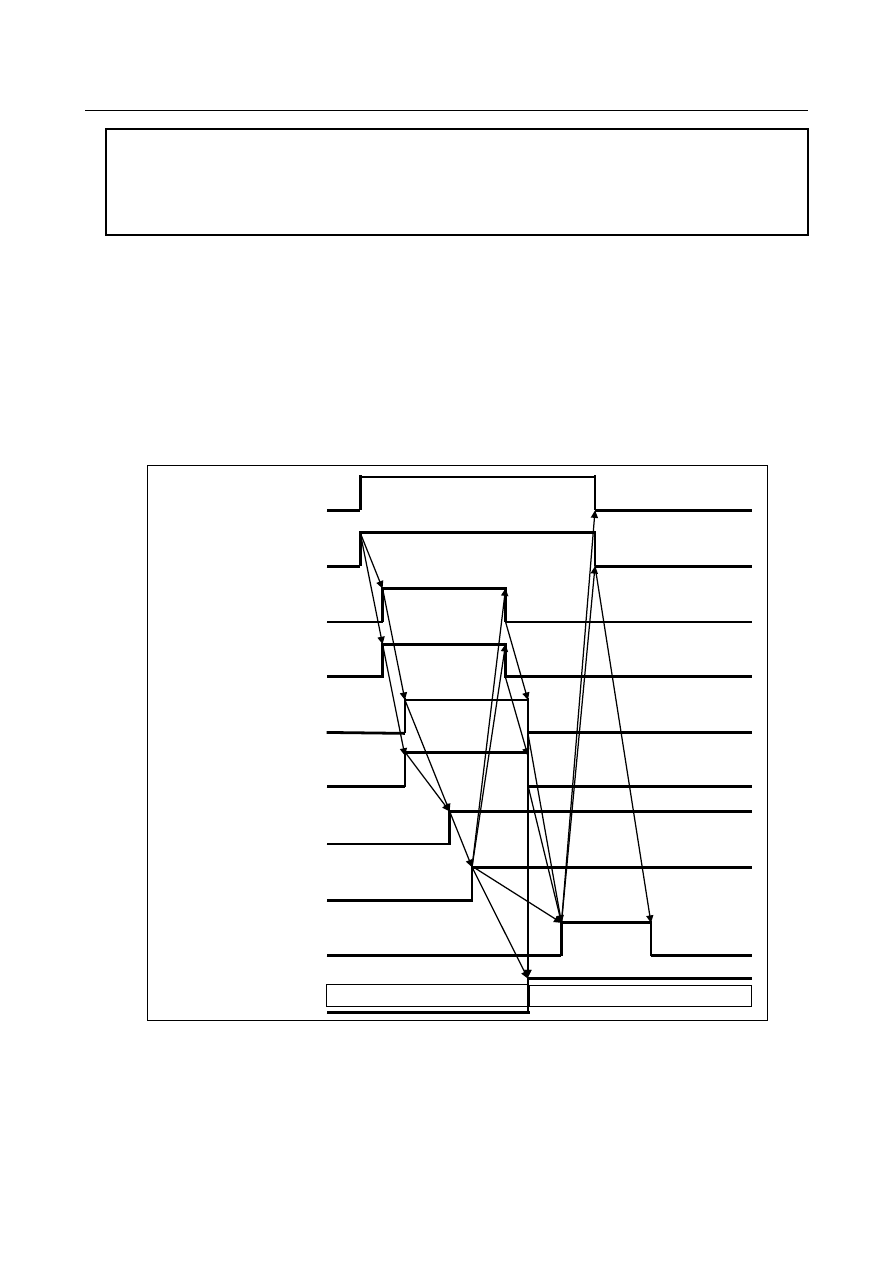
[Switch procedure of dual control axes switching signal] 
 

To switch the dual control axes switching signal from “0” to “1”, switch the signal according to the 

following procedure. 

(1)


Set the controlled axis detach signals DTCHx <Gn124.x> for a real axis and an imaginary axis to 
“1”, using the M code as a trigger. 

(2)


Set the dual control axes switching signal SVMWCx <Gn687.x> to “1”, when the controlled axis 
detach status signals MDTCHx <Fn110.x> for a real axis and an imaginary axis are “1”. 

(3)


Set the controlled axis detach signals DTCHx <Gn124.x> for a real axis and an imaginary axis to 
“0”, when the dual control axes status signal SVMWSx <Fn687.x> is “1”. 

(4)


Perform the FIN processing for the M code. 


The controlled axis detach 

status signal for an imaginary 

axis 

MDTCHx <Fn110.x> 

Imaginary axis 

Real axis 

The controlled axis detach 

signal for a real axis 

DTCHx <Gn124.x> 

The controlled axis detach 

status signal for a real axis 

MDTCHx <Fn110.x> 

The dual control axes 

switching signal   

SVMWCx <Gn687.x> 

M code for turning the dual 

control axes switching signal 

ON 

<Fn010 to 013> 

M code 

MF <Fn007.0> 

FIN <Gn004.3> 

The dual control axes 

status signal 

SVMWSx <Fn687.x> 

The axis connected with 

servo motor 

The controlled axis detach 

signal for an imaginary axis 

DTCHx <Gn124.x> 


Fig. 1.16 (d) Timing chart (The dual control axes switching signal SVMWCx <Gn687.x> “0” 

→ “1”) 


To switch when the dual control axes switching signal from “1” to “0”, switch the signal according to 
the following procedure. 
(1)


Set the controlled axis detach signals DTCHx <Gn124.x> for a real axis and an imaginary axis to 
“1”, using the M code as a trigger. 

(2)


Set the dual control axes switching signal SVMWCx <Gn687.x> to “0”, if the controlled axis 
detach status signals MDTCHx <Fn110.x> for a real axis and an imaginary axis are “1”. 

B-64693EN-1/01


1. AXIS CONTROL


- 491 - 

(3)


Set the controlled axis detach signals DTCHx <Gn124.x> for a real axis and an imaginary axis to 
“0”, if the dual control axes status signal SVMWSx <Fn687.x> is “0”. 

(4)


Perform the FIN processing for the M code. 


The controlled axis detach 

status signal for an imaginary 

axis 

MDTCHx <Fn110.x> 

M code 

Real axis 

Imaginary axis 

The controlled axis detach 

signal for a real axis 

DTCHx <Gn124.x> 

The controlled axis detach 

status signal for a real axis 

MDTCHx <Fn110.x> 

The dual control axes 

switching signal   

SVMWCx <Gn687.x> 

M code for turning the dual 

control axes switching signal 

OFF 

<Fn010 to 013> 

MF <Fn007.0> 

FIN <Gn004.3> 

The dual control axes 

status signal 

SVMWSx <Fn687.x> 

The axis connected with 

servo motor 

The controlled axis detach 

signal for an imaginary axis 

DTCHx <Gn124.x> 


Fig. 1.16 (e) Timing chart (The dual control axes switching signal SVMWCx <Gn687.x> “1” 

→ “0”) 


Use with absolute position detection 

To set the zero point of an absolute position detector, perform the manual reference position return at the 
selected axis. Perform the manual reference position return for a real axis and an imaginary axis as the 
selected axis. 
If the zero point of an absolute position detector is set, the manual reference position return is 
unnecessary when the dual control axes switching signal SVMWCx <Gn687.x> is switched. 
 

Without absolute position detection 

When the dual control axes switching signal SVMWCx <Gn687.x> is switched, the reference position is 
lost. The manual reference position return must be performed by the selected axis before the move 
command. If specifying the move command without reference position return, alarm PS0224 “ZERO 
RETURN NOT FINISHED” is issued. 
 

Restrictions 

Dual control axes switching cannot be used together with the following functions. 
-


Dual Check Safety 

-


Angular axis control 

-


Tandem control 

-


Dual position feedback 

1. AXIS CONTROL


B-64693EN-1/01


- 492 - 

-


Semi-Full error monitoring 

 
The dual control axes switching cannot be used for multiple winding motor. 
 
Disable the following functions, before the dual control axes switching signal SVMWCx <Gn687.x> is 
switched. 
-


Synchronous control and composite control 

-


Superimposed control 

-


Axis synchronous control 

-


Flexible synchronization control 

-


Electronic gear box 

-


Axis control by PMC 

-


Spindle control with servo motor 


B-64693EN-1/01


1. AXIS CONTROL


- 493 - 

NOTE 

1  To disable the display of non-selected axis, delete the current position indication 

for the non-selected axis by using bit 0 (NDPx) of parameter No.3115. 

2  The setting of bit 0 (ROTx) and 1 (ROSx) of parameter No.1006 should be same 

setting for both a real axis and an imaginary axis. If the setting is different, the 
machine coordinates might not be correctly updated at dual control axes 
switching signal SVMWCx <Gn687.x> switching. 

3  If the controlled axis detach status signals MDTCHx <Fn110.x> for a real axis 

and an imaginary axis are not “1” while dual control axes switching signal 
SVMWCx <Gn687.x> is switched, alarm SV0401 “IMPROPER V_READY OFF” 
is issued. 

4  In automatic operation, set the M code for dual control axes switching signal on 

or off to the M code preventing buffering. (Parameters Nos.3411 to 3432) 

5  An alarm occurs at the time of a mechanical adjustment, so on and off of dual 

control axes switching signal perform a time chart on Fig. 1.16 (d) and Fig. 1.16 
(e) manually. 

6  If the dual control axes switching is executed while excitation of the motor is on, 

alarm SV0417 “ILL DGTL SERVO PARAMETER” is issued. (Detail number of 
diagnosis data No.352: 4379) 

7  It is necessary to change bit 1 to 4 of parameter No.2013 and bit 1 to 4 of 

parameter No.2014 for an axis of the dual control axes switching according to 
the motor model. If the standard parameters for the motor model are the same 
as the values described in the before change column in the below table, change 
to the values described in the after change column. 

No.2013 #4,#3,#2#1 

No.2014 #4,#3,#2,#1 


Before change 


After change 

1, 0, 0, 1 

→ 

1, 0, 1, 0 

0, 1, 1, 1 

→ 

1, 0, 0, 0 

0, 1, 0, 1 

→ 

0, 1, 1, 0 

0, 0, 1, 1 

→ 

0, 1, 0, 0 

0, 0, 0, 1 

→ 

0, 0, 1, 0 

8  To get the frequency response using SERVO GUIDE, because the serial 

feedback dummy function (bit 0 (DMYx) of parameter No.2009) is effective to an 
imaginary axis, it is not possible to measure. To get the frequency response with 
imaginary axis, temporarily invalidate the serial feedback dummy function (bit 0 
(DMYx) of parameter No.2009) for an imaginary axis after power on and 
measure it. After completing the measurement, reset to effective the serial 
feedback dummy function (bit 0 (DMYx) of parameter No.2009 = 1). 

9  In actual speed display, a synthetic speed of real axis and imaginary axis is 

displayed. In order to exclude imaginary axis speed from the actual speed 
display, set actual speed display axis selection signals *ACTF1 to *ACTF8 
<Gn580> to “1” about the imaginary axis. 


1. AXIS CONTROL


B-64693EN-1/01


- 494 - 

Parameter 

1023 


Number of the servo axis for each axis 


NOTE 


When this parameter is set, the power must be turned off before 
operation is continued. 


[Input type]  Parameter input 


[Data type]  Byte axis 

[Valid data range]  0 to 80 

This parameter associates each control axis with a specific servo axis. Specify values 
1+8n, 2+8n, 3+8n, 4+8n, 5+8n, and 6+8n (n = 0, 1, 2, …, 9) like 1, 2, 3, 4, 5, …, 77, and 
78. 
The control axis number is the order number that is used for setting the axis-type 
parameters or axis-type machine signals 
For dual control  axes switching, two axes  need to be specified  as one pair. So, make a 
setting as described below. 
For a real axis, set an odd (1, 3, 5, 9, ...) servo axis number. For an imaginary axis to be 
paired, set a value obtained by adding 1 to the value set for the real axis. 


#7 

#6 

#5 

#4 

#3 

#2 

#1 

#0 

2009 


DMYx 


[Input type]  Parameter input 


[Data type]  Bit axis 


#0  DMYx

  The serial feedback dummy function is: 

0: 

Not used. 

1: 

Used. 

Set this parameter for the imaginary axis. 
 

NOTE 


The setting of this parameter becomes valid after the power is turned 
off then back on. 


#7 

#6 

#5 

#4 

#3 

#2 

#1 

#0 

2437 


DCHx 


[Input type]  Parameter input 


[Data type]  Bit axis 


#3  DCHx

  The dual control axes switching function is: 

0: 

Disabled. 

1: 

Enabled. 

Set this parameter to both axes of the real axis and the imaginary axis. 


#7 

#6 

#5 

#4 

#3 

#2 

#1 

#0 

2570 


DCFULLx 


[Input type]  Parameter input 


[Data type]  Bit axis 


B-64693EN-1/01


1. AXIS CONTROL


- 495 - 


#3  DCFULLx

  In the dual control axes switching function, one scale is: 

0: 

Shared with the real axis and the imaginary axis. 

1: 

Not shared with the real axis and the imaginary axis. 

Set this parameter only for the imaginary axis. 


NOTE 


In the case of having an individual scale with the real axis and 
imaginary axis, set this bit to 1. 


24096 


Connector number for the 1st or 9th separate detector interface unit 


24097 


Connector number for the 2nd or 10th separate detector interface unit 


24098 


Connector number for the 3rd or 11th separate detector interface unit 


24099 


Connector number for the 4th or 12th separate detector interface unit 


24100 


Connector number for the 5th separate detector interface unit 


24101 


Connector number for the 6th separate detector interface unit 


24102 


Connector number for the 7th separate detector interface unit 


24103 


Connector number for the 8th separate detector interface unit 


NOTE 


When these parameters are set, the power must be turned off before 
operation is continued. 


[Input type]  Parameter input 


[Data type]  Byte axis 

[Valid data range]  0 to 8 

Set a connector number for the connector to which a separate detector interface unit is 
attached if the separate detector interface unit is to be used. The following table lists the 
necessary settings. Be sure to specify 0 for connectors not in use. 
 

Correspondence between connectors and connector numbers 

Connector 

Connector number 

JF101 

JF102 

JF103 

JF104 

JF105 

JF106 

JF107 

JF108 


1. AXIS CONTROL


B-64693EN-1/01


- 496 - 

(Setting example) 

Controlled 

axis 

Connector to which each separate 

detector interface unit is attached 

Parameter setting 

1st 

connector 

2nd 

connector 

5th 

connector 

6th 

connector 

No. 

24096 

No. 

24097 

No. 

24100 

No. 

24101 

X1 

JF101 


Y1 


JF102 


Z1 


JF102 


X2 


JF101 


Y2 


JF101 

Z2 


A1 


JF101 


B1 


JF102 

C1 


JF104 


A2 

JF102 


B2 


JF103 


C2 


JF103 


NOTE 

1  Specify these parameters when separate detector interface units 

are used.   

2  Parameters Nos. 24096 to 24103 are specified automatically when 

data is entered on the FSSB setting screen if the FSSB setting mode 
in use is the automatic setting mode (bit 0 (FMD) of parameter No. 
1902 = 0). If the manual setting 2 mode (bit 0 (FMD) of parameter 
No. 1902) = 1), specify the parameters directly.   


Alarm and message 

Number 

Message 

Description 

PS0224 

ZERO RETURN NOT FINISHED 

A reference return has not been performed before the start of 
automatic operation. 
(Only when bit 0 (ZRNx) of parameter No.1005 is 0) 
Perform a reference position return. 

SV0401 

IMPROPER V_READY OFF 

Although the ready signal (PRDY) of the position control was 
ON, the ready signal (VRDY) of the velocity control was OFF. 

SV0417 

ILL DGTL SERVO PARAMETER 

A digital servo parameter setting is incorrect. 


Signal 

Actual speed display axis selection signals *ACTF1 to *ACTF8 <Gn580> 

  [Classification]  Input signal 
 

[Function]  These signals specify whether the movement speed of each axis is added to the display of 

actual speed. 


[Operation]  The movement speed of the axis for which 1 is set is not added to the display of actual 

speed. 


Dual control axes switching signal SVMWC1 to SVMWC8 <Gn687> 

  [Classification]  Input signal 
 

[Function]  These signals switch the selected axes in dual control axes. 


[Operation]  When this signal is set to “0”, the real axis becomes selected axis. And the imaginary axis 

becomes non-selected axis. 


  When this signal is set to “1”, the imaginary axis becomes selected axis. And the real axis 

becomes non-selected axis. 


B-64693EN-1/01


1. AXIS CONTROL


- 497 - 


Dual control axes status signal SVMWS1 to SVMWS8 <Fn687> 

  [Classification]  Output signal 
 

[Function]  This signal notifies the status of the dual control axes. 


[Operation]  This signal becomes “0” when: 


  - The real axis is selected axis, and the imaginary axis is non-selected axis. 


  This signal becomes “1” when: 


  - The imaginary axis is selected axis, and the real axis is non-selected axis. 


Signal address 


#7 

#6 

#5 

#4 

#3 

#2 

#1 

#0 

Gn580 


*ACTF8 

*ACTF7 

*ACTF6 

*ACTF5 

*ACTF4 

*ACTF3 

*ACTF2 

*ACTF1 


#7 

#6 

#5 

#4 

#3 

#2 

#1 

#0 

Gn687 


SVMWC8 

SVMWC7 

SVMWC6 

SVMWC5 

SVMWC4 

SVMWC3 

SVMWC2 

SVMWC1 


#7 

#6 

#5 

#4 

#3 

#2 

#1 

#0 

Fn687 


SVMWS8 

SVMWS7 

SVMWS6 

SVMWS5 

SVMWS4 

SVMWS3 

SVMWS2 

SVMWS1 


NOTE 


The signal (Gn687, Fn687) for the real axis can be used. The signal 
for the imaginary axis cannot be used.   


1.17 

VELOCITY FEED FORWARD COMPENSATION FUNCTION 

Overview 

Velocity feed forward coefficient can be adjusted according to the machine coordinate value of the 
moving axis specified by parameter No.11821. 
 

Explanation 

Velocity feed forward coefficient of the compensation axis can be adjusted according to the machine 
coordinate value of the moving axis specified by parameter No.11821 with this function. 
 
Velocity feed forward coefficient of the compensation axis is determined by the following formula. 


VFF  

: Velocity feed forward coefficient 


VFF

: Velocity feed forward coefficient parameter (No.2069, 2145) 


: Compensation coefficient 

 
Compensation coefficient of the compensation axis is set with the following parameters. 
 

Table 1.17 (a) Compensation coefficient setting parameter 


Parameter 

Machine coordinate of moving axis 

No.14270 to No.14279 

Compensation coefficient of compensation axis 

No.14280 to No.14289 

 
Example 1) 
When setting the parameter in Table 1.17 (b) below, compensation coefficients of the compensation axis 
are as shown in Fig. 1.17 (a). 


Content      ..     65      66      67      68     ..