FANUC Series 0i-MODEL F Plus. CONNECTION MANUAL (FUNCTION) - page 65
 

  Index      Manuals     FANUC Series 0i-MODEL F Plus. CONNECTION MANUAL (FUNCTION) B-64693EN-1/01


Search            copyright infringement  


Content      ..     63      64      65      66     ..


FANUC Series 0i-MODEL F Plus. CONNECTION MANUAL (FUNCTION) - page 65


1. AXIS CONTROL


B-64693EN-1/01


- 474 - 

- Omission of movements to point R and to the center point 

By setting 1 to bit 0 (OST) and 1 (FFS) of parameters No.25651, if oscillation motion is started by G81.1 
command,  movements to point R and to the center point can be omitted, and oscillation motion can be 
immediately started. In this case, the first dead point is as follows. 
 

State before G81.1 command 

The first dead point 

In case of the first command of oscillation motion  after the power is turned on or in the 
state of reset. 

Lower dead point 

In the state that command of cancel was specified on the way to lower dead point at last 
oscillation motion. 
In the state that command of cancel was specified on the way to upper dead point at last 
oscillation motion. 

Upper dead point 


- Acceleration/deceleration 

Linear  acceleration/deceleration  by parameter (No.25653)  is applied to the movement from point R to 
center point or the motion till stop.   
Moreover,  when override is changed during oscillation motion, the acceleration/deceleration set by 
parameter (No.25653) is effective. 
Acceleration/deceleration of sine curve feedrate control is enabled on oscillation motion. 
 

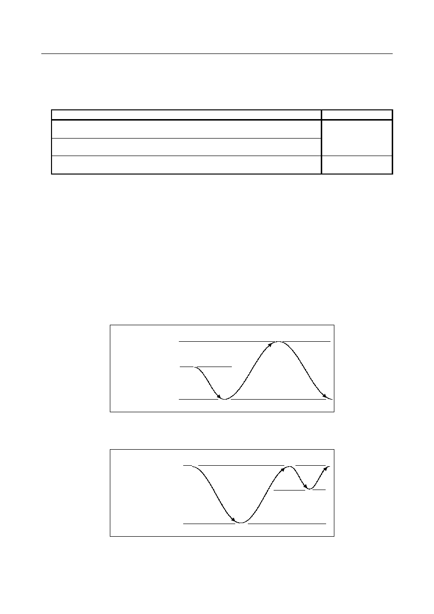
- Oscillation after the upper dead point or lower dead point has been changed 

When the upper dead point or lower dead point is changed while oscillation motion is being performed, 
the tool moves to the dead points specified by the old data. Then, oscillation motion is changed to the new 
one using the new data. 
The following describes the operations performed after the data has been changed. 
 
(1)  When the upper dead point is changed during movement from the upper dead point to the lower 

dead point 


New upper dead point 

Previous upper dead point 

Lower dead point 


The tool first moves to the lower dead point, then to the new upper dead point. 

 
(2)  When the lower dead point is changed during movement from the upper dead point to the lower 

dead point 


Upper dead point 

New lower dead point 

Previous lower dead point 


The tool first moves to the previous lower dead point, then to the upper dead point, and finally to the 
new lower dead point. 


B-64693EN-1/01


1. AXIS CONTROL


- 475 - 

(3)  When the upper dead point is changed during movement from the lower dead point to the upper 

dead point 


New upper dead point 

Previous upper dead point 

Lower dead point 


The tool first moves to the previous upper dead point, then to the lower dead point, and finally to the 
new upper dead point. 

 
(4)  When the lower dead point is changed during movement from the lower dead point to the upper 

dead point 


Upper dead point 

Previous lower dead point 

New lower dead point 


The tool first moves to the upper dead point, then to the new lower dead point. 


- Look-ahead feed forward function 

Look-ahead feed forward function can be effective for oscillation motion. 
Refer to the following manual for details of the setting method and so on. 

- FANUC AC SERVO MOTOR 

α

i

 series PARAMETER MANUAL (B-65270EN) 

     "Look-ahead feed forward function" 


- Mode switching during oscillation motion 

If the mode is changed during oscillation motion, oscillation motion does not stop. In manual mode, the 
oscillation axis cannot be moved manually. It cannot also be moved manually by means of the handle 
interrupt. 
 

- Single block signal 

Even when single block signal SBK<Gn046.1> is input during oscillation motion, oscillation continues. 
 

- Interlock signal 

Interlock signal for all axes *IT<Gn008.0> or Interlock signals for each axis *ITx<Gn130> is valid to the 
oscillation axis in oscillation mode.  However, Interlock signal for each axis direction +MITx/-MITx 
<Gn132/Gn134, X004.2 to X004.5> is invalid to the oscillation axis in oscillation mode. 
If interlock is effective  to the oscillation axis during oscillation motion, the oscillation axis decelerates 
and stops immediately. 
 

- Flexible synchronization control 

Flexible synchronization control whose master axis is the oscillation axis can be used. 
If Look-ahead feed forward function is used, it is necessary to set the parameter also to the slave axis as 
well as the master axis.   
However, Inter-path flexible synchronization control with oscillation axis cannot be used. 

1. AXIS CONTROL


B-64693EN-1/01


- 476 - 

- Axis synchronous control 

Axis synchronous control whose master axis is the oscillation axis can be used. 
If Look-ahead feed forward function is used, it is necessary to set the parameters also to the slave axis as 
well as the master axis. 
 

- Machine lock during oscillation motion 

"If all-axis machine lock signal MLK<Gn044.1> or each-axis machine lock signals MLK1 to 
MLK8<Gn108> are turned ON or OFF during oscillation movement,  an alarm PS5050 
"ILL-COMMAND IN G81.1 MODE" is issued. 
After an alarm PS5050 is issued, oscillation axes move to the point R, then the axes become the machine 
lock state. " 
 

  - Diameter and Radius Setting 

The command and the parameter value (coordinates, feedrate)  follow the diameter  and  radius  setting of 
the oscillation axis. Actual data value (feedrate F) is displayed by the radius. 
 

Limitation 

- Workpiece coordinate system 

While oscillation is being performed, do not change the workpiece coordinate system for the oscillation 
axis. 
 

- PMC axis 

When the oscillation axis is operating as the PMC axis, oscillation is not started. 
 

- Mirror image 

Never attempt to apply the mirror image function about the oscillation axis. 
 

- Move command during oscillation motion 

If a move command is specified for the oscillation axis while oscillation motion is being performed, an 
alarm (PS5050) "ILL-COMMAND IN G81.1 MODE" is issued. 
 

- Canned Cycle 

While oscillation is being performed, do not specify canned cycle. 
 

- Program restart / Quick program restart 

When a program contains G codes for starting oscillation (G81.1) and stopping oscillation (G80), an 
attempt to restart that program results in an alarm (PS5050) being output. 
When a program that does not include the oscillation axis is restarted during oscillation motion, the 
coordinates and amount of travel set for the oscillation axis are not affected after the restart of the 
program. 
 

- Rotation axis 

Oscillation operation cannot be used with rotation axis (type-A). 
 

- Inch/Metric conversion commands 

While oscillation is being performed, do not specifyinch/metric conversion commands. 
 

- General purpose retract 

While oscillation is being performed, do not perform retraction. The oscillation motion does not stop by 
retraction. 
 

- Stored stroke check 

Stored stroke check 1-I (parameter Nos. 1320 and 1321) is effective during oscillation motion. 

B-64693EN-1/01


1. AXIS CONTROL


- 477 - 

- Arbitrary angular axis control 

Do not set angular axis and perpendicular axis of arbitrary angular axis control to oscillation axis. 
 

- Three-dimensional coordinate conversion / Tilted working plane indexing 

command 

While oscillation is being performed, do not specify  three-dimensional  coordinate  conversion / tilted 
working plane indexing command. 
 

- Cs contour control axis 

Do not set Cs contour control axis to oscillation axis. If oscillation is specified for Cs contour control axis, 
an alarm (PS5050) "ILL-COMMAND IN G81.1 MODE" is issued. 


Synchronous/Composite control 

Do not set synchronous/composite control axis to oscillation axis. 
 

- Polygon turning 

Do not set 

control axis for polygon turning

 to oscillation axis. 


- Manual handle interrupt 

Manual handle interrupt is invalid to the axis in the oscillation mode. 
(The slave axis of Flexible synchronization control which has oscillation axis as master or Axis 
synchronous control is contained) 


- Constant surface speed control 

Do not set 

reference axis for constant surface speed control

 to oscillation axis. 


- Polar coordinate interpolation 

Do not set 

linear/rotation axis for polar coordinate interpolation

 to oscillation axis.


Example 

To start oscillation, specify the following command: 

G90 G81.1 Z100. Q-25. R10. F3000. ; 

The tool moves to point R (Z+R = Z110.0) with rapid traverse feedrate. 

Next, move to center point (Z87.5) between upper dead point (Z100.0) and lower dead point (Z+Q = 
Z75.0) at oscillation base feedrate (F3000.0 [mm/min]). 

Then, perform repeated movement along the Z-axis between the upper dead point and the lower 
dead point with sine curve feedrate 

F

 by Exp. 1. Oscillation override 

k

 is enabled. 


1. AXIS CONTROL


B-64693EN-1/01


- 478 - 


Lower dead point (Z75.0) 

Upper dead point (Z100.0) 

Point R (Z110.0) 

Center point between 

upper and lower dead points 

(Z87.5) 

Position 

Feedrate 

F

 = 3000.0 [mm/min] 

F

 = -3000.0 [mm/min] 

F

 = 0.0 [mm/min] 

(

k

 = 1.0 (100%)) 


To cancel oscillation motion, specify the following command: 

G80 ; 

Motion of cancel is as follows. 
  Bit 0 (OST) of parameter No.25651 is   

0: The tool moves to point R and stops. 
1: The tool decelerates and stops. 


Superimposed control 

If oscillation axis is set to master axis and superimposed control is started, it is necessary on the 
corresponding path to be executing superimposed ahead mode  by  adjusting  superimposed ahead signal 
OVLN <Gn531.4> to "1". Set superimposed ahead signals OVLN to "1" in each path, if paths of master 
axis and slave axis are different. 
Refer to the following manual for details of the setting method and so on. 

"FANUC  Series  0

i

-F Plus  CONNECTION MANUAL (FUNCTION)" (B-64693EN-1) 

"Superimposed Control" 

 
Example) 

(1) In the case that paths of master axis and slave axis are the same. 

M210 
M60 
G81.1 
 
G80 
M61 
M211 

…Superimposed ahead mode ON 
…Starts superimposed control 
…Starts oscillation motion 
 
…Cancels oscillation motion 
…Cancels superimposed control 
…Superimposed ahead mode OFF 


B-64693EN-1/01


1. AXIS CONTROL


- 479 - 

(2) In the case that paths of master axis and slave axis are different. 

Path of the master axis 

Path of the slave axis 

M100P12 
M210 
 
M101P12 
G81.1 
 
G80 
M103P12 
 
M211 
M104P12 

…Waiting 
…Superimposed ahead mode ON 
 
…Waiting 
…Starts oscillation motion 
 
…Cancels oscillation motion 
…Waiting 
 
…Superimposed ahead mode OFF 
…Waiting 

M100P12 
M212 
M60 
M101P12 


M103P12 
M61 
M213 
M104P12 

…Waiting 
…Superimposed ahead mode ON 
…Starts superimposed control 
…Waiting 


…Waiting 
…Cancels superimposed control 
…Superimposed ahead mode OFF 
…Waiting 


NOTE 

1  To switch superimposed ahead signal ON/OFF, it is necessary to stop all 

axes (except for PMC axis) of path where this signal is switched. 

2  Switch ON/OFF the superimposed ahead mode after the superimposed 

control has been canceled in slave path. 

3  The following functions cannot be commanded in the path to which the 

superimposed ahead mode is effective.   
  - Reference return in Cs contouring control (G00, G28) 
  - Skip function (G31) 
  - Automatic tool length measurement / Automatic tool offset function 
  - Automatic reference return operation of low-speed type (G28) 
  - High speed program check function 


These functions can be commanded, when superimposed control and 
superimposed ahead mode are off. 

4  The M code for superimposed ahead mode must be assigned to M codes 

preventing buffering. (Parameter Nos. 3411 to 3432) 

5  Oscillation axis cannot be set to slave axis. If oscillation axis is set to slave 

axis and oscillation motion is started, an alarm PS5050 is issued. 


1. AXIS CONTROL


B-64693EN-1/01


- 480 - 

Starting sequence of the superimposed ahead mode and superimposed control. 


Superimposed control axis 
selection signal OVLS 

Superimposed control mode 
signal SYN


End signal FIN 


Strobe signal MF 


Superimposed control start M 
command 

Waiting between paths 

Superimposed ahead signal 
OVLN 

End signal FIN 


Strobe signal MF 


Superimposed ahead mode ON 
M command 

Superimposed ahead under way 
signal OVLNS 


1. 

When the M code for enabling superimposed ahead mode is specified and superimposed ahead 
signal OVLN is set to "1", Superimposed ahead under way signal OVLNS becomes "1". 

2. 

When superimposed ahead under way signal OVLNS becomes "1", operate the end signal FIN in 
order to complete the procedure. 

3. 

Command the waiting M code in both paths of master axis and slave axis. (If paths of master axis 
and slave axis belong to the same path, the M code is omitted.) 

4. 

When the M code for enabling superimposed control is specified  and superimposed control axis 
select signal OVLS is set to "1", superimposed control starts. And the superimposed control mode 
signal SYN becomes "1". 

5. 

When superimposed control mode signal SYN becomes "1", operate the end signal FIN in order to 
complete the procedure. 


B-64693EN-1/01


1. AXIS CONTROL


- 481 - 

Canceling sequence of the superimposed ahead mode and superimposed control. 


Superimposed ahead mode OFF 

M command 

Superimposed control cancel 

M command 

Superimposed ahead signal 

OVLN 

Superimposed ahead under way 

signal OVLNS 

End signal 

FIN


End signal 

FIN


Strobe signal 

MF


Strobe signal 

MF


Superimposed control axis 

selection signal OVLS 

Superimposed control mode 

signal SYN


Waiting between paths 


1. 

When the M code for canceling the superimposed control is specified, and superimposed control axis 
select signal OVLS is set to "0", superimposed control will be canceled (superimposed control under 
way signal SYN turn to “0”). 

2. 

When superimposed control mode signal SYN becomes "0", operate the end signal FIN in order to 
complete the procedure. 

3. 

Command the waiting M code in both paths of master axis and slave axis. (If paths of master axis 
and slave axis belong the same path, the M code is omitted.) 

4. 

When the M code for disabling superimposed ahead mode is specified and superimposed ahead 
signal OVLN is set to "0", superimposed ahead mode is canceled (advanced superimposition mode 
signal OVLNS turn to “0” ). 

5. 

When superimposed ahead under way signal OVLNS becomes to "0", operate the end signal FIN in 
order to complete procedure. 


Signal 

Oscillation start signal CHPST <Gn051.6> 


[Classification]  Input signal 


[Function]  Starts and stops oscillation.


[Operation]  Setting this signal to "1" starts oscillation. 


  Setting this signal to "0" during oscillation motion causes oscillation to be stopped.


Content      ..     63      64      65      66     ..