FANUC Series 0i-MODEL F Plus. CONNECTION MANUAL (FUNCTION) - page 64
 

  Index      Manuals     FANUC Series 0i-MODEL F Plus. CONNECTION MANUAL (FUNCTION) B-64693EN-1/01


Search            copyright infringement  


Content      ..     62      63      64      65     ..


FANUC Series 0i-MODEL F Plus. CONNECTION MANUAL (FUNCTION) - page 64


1. AXIS CONTROL


B-64693EN-1/01


- 466 - 

-


When all axes in a path are specified for read/write, target axes are determined by the initial path 

numbers of each axis. Furthermore, the order of each axis data and the axis number read by 
function code 433 (CNC alarm detail read) depend on the initial axis number.   

-


The number of axes in a path acquired by function code 0 (reading CNC system information) 

depend on the initial path numbers of each axis. 

 
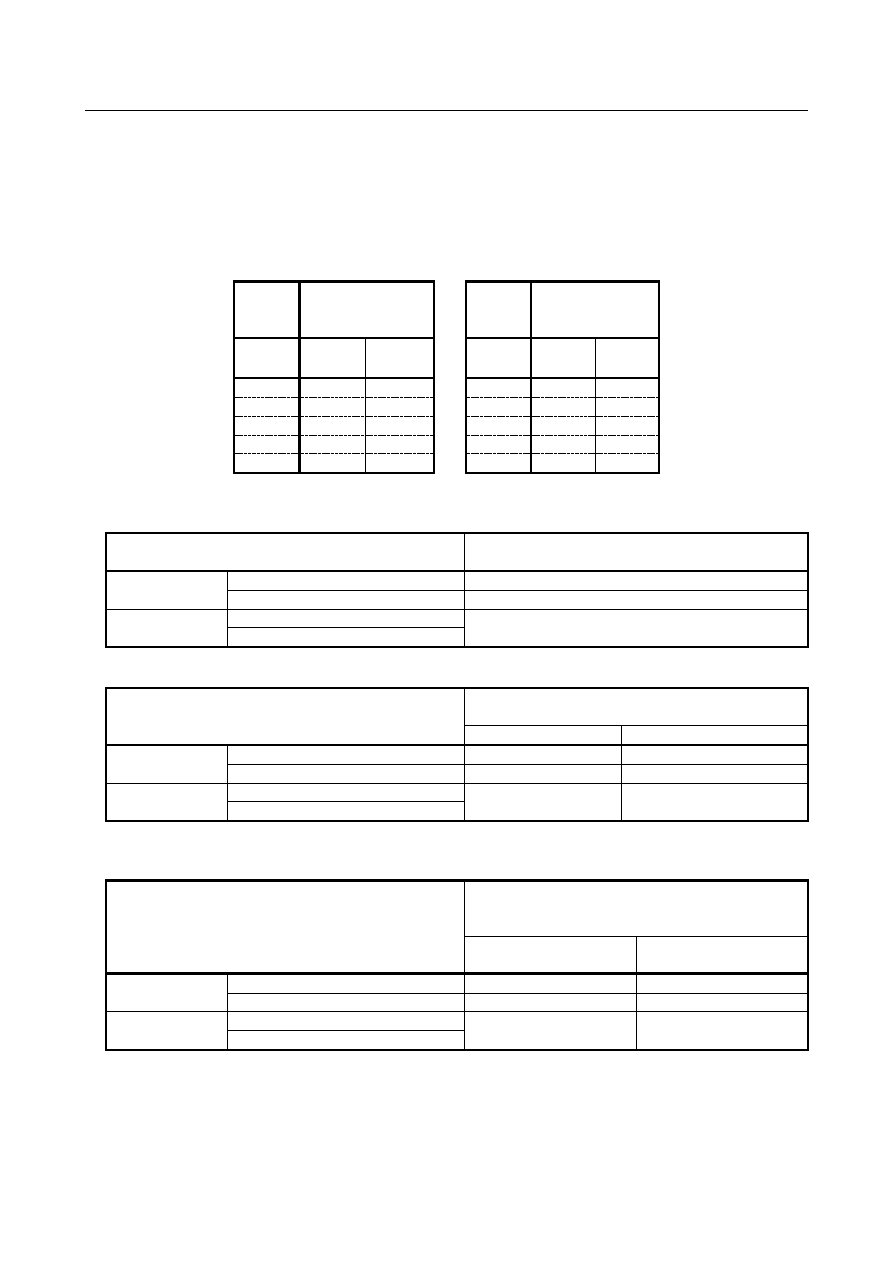
Example) 

Flexible path axis assignment is executed as following table. 


Before flexible 

path axis 

assignment   


After flexible 

path axis 

assignment   

Axis 

number 

Path 1 

Path 2 

Axis 

number 

Path 1 

Path 2 

X1 

X2 

X1 

X2 

Y1 

Y2 

Y1 

Y2 

Z1 

Z2 

Z1 

Z2 

A1 


A1 

'C' 

'C' 


In this example, to read the data of C-axis, specify the axis number and the path number as following 
table.   


The axis number and path number   

specified to read the data of C-axis   

Parameter PPW 
(No.11563#7)=0 

Before flexible path axis assignment 

5th axis in the path 1 

After flexible path axis assignment 

4th axis in the path 2 

Parameter PPW 
(No.11563#7)=1 

Before flexible path axis assignment 

5th axis in the path 1 

After flexible path axis assignment 

 
When all axes in the path is specified for read/write, target axes are shown in the following table. 


Target axes of read/write 

with all axes are specified 

Path 1 

Path 2 

Parameter PPW 
(No.11563#7)=0 

Before flexible path axis assignment 

X1,Y1,Z1,A1,C 

X2,Y2,Z2,A2 

After flexible path axis assignment 

X1,Y1,Z1,A1 

X2,Y2,Z2,A2,C 

Parameter PPW 
(No.11563#7)=1 

Before flexible path axis assignment 

X1,Y1,Z1,A1,C 

X2,Y2,Z2,A2 

After flexible path axis assignment 


The numbers of axes in each path  are read by function code 0 (reading CNC system information) as 
shown in the following table. 


The numbers of axes in each path   

read by function code 0 (reading CNC system 

information)   

Number of axes in path 

Number of axes in path 

Parameter PPW 
(No.11563#7)=0 

Before flexible path axis assignment 

After flexible path axis assignment 

Parameter PPW 
(No.11563#7)=1 

Before flexible path axis assignment 

After flexible path axis assignment 


B-64693EN-1/01


1. AXIS CONTROL


- 467 - 

Supported PMC WINDOW functions 

Supported PMC WINDOW functions are shown in following table. 

Description 

Function 

code 

Response 

R/W 

Reading CNC system information 

High-speed 

Reading a work piece origin offset value 

15 

High-speed 

Writing a work piece origin offset value 

16 

Low-speed 

Reading a parameter 

17,154 

High-speed 

Writing a parameter 

18 

Low-speed 

Reading a real type parameter 

321 

High-speed 

Writing a real type parameter 

323 

Low-speed 

Reading setting data 

19,155 

High-speed 

Writing setting data 

20 

Low-speed 

Reading diagnosis data 

33 

Low-speed 

Reading detailed information of CNC 

433 

Low-speed 

Reading the absolute position (absolute coordinates) of controlled axes 

27 

High-speed 

Reading the machine position (machine coordinates) of controlled axes 

28 

High-speed 

Reading a skip position (stop coordinates of skip operation (G31))   

of controlled axes 

29 

High-speed 

Reading the servo delay for controlled axes 

30 

High-speed 

Reading the acceleration/deceleration delay on controlled axes 

31 

High-speed 

Reading the feed motor load current value (A/D conversion data) 

34 

High-speed 

Reading the relative position on a controlled axis 

74 

High-speed 

Reading the remaining travel on a controlled axis 

75 

High-speed 

Reading the actual velocity of each controlled axes 

91 

High-speed 

Entering torque limit data for the digital servo motor 

152 

Low-speed 

Reading the actual speed on a controlled axis 

207 

High-speed 

Reading the estimate disturbance torque data 

211 

High-speed 

Presetting the relative coordinate 

249 

Low-speed 

Reading the actual machine position of controlled axes 

428 

High-speed 

Reading the command value of axes 

446 

High-speed 


Limitation 

Least input increment   

When the improvement is valid (No.11563#7=1) and the path number of the axis is changed by flexible 
path axis assignment, to treat the data of this axis by PMC window function, least input increment of the 
current path must be same as least input increment of the initial path.   

 
Example) 

Flexible path axis assignment is executed as following table. 


Before flexible path axis 

assignment 


After flexible path axis 

assignment 

Axis 

number 

Path 1 

Path 2 

Axis 

number 

Path 1 

Path 2 

X1 

X2 

X1 

X2 

Y1 

Y2 

Y1 

Y2 

Z1 

Z2 

Z1 

Z2 

A1 


A1 

'C' 

'C' 


In this example, to execute read/write of the data of C-axis by PMC window function, least input 
increment of path 1 must be same as least input increment of path 2.   

1. AXIS CONTROL


B-64693EN-1/01


- 468 - 


Parameter 


#7 

#6 

#5 

#4 

#3 

#2 

#1 

#0 

11563 


PPW 


[Input type]  Parameter input 


[Data type]  Bit 


#7  PPW

  PMC window function with execution of flexible path axis assignment behaves according 

to: 
0: 

The path number and the axis number changed by flexible path axis assignment.   

1: 

The path number  and  the  axis number of the  initial state (setting of the parameter 
No.981). 


NOTE 


When this parameter is set, the power must be turned off before 
operation is continued. 


1.15 

HIGH PRECISION OSCILLATION FUNCTION 

Overview 

In this function, the feedrate of oscillation axis (equivalent to a chopping axis that is moved vertically and 
repeatedly for grinding) changes along sine curve. This function is effective to improve, the accuracy of 
movement between upper dead point and lower dead point. 
Moreover, look-ahead feed forward function can be applied to oscillation motion. Then the servo delay 
can be almost eliminated  and  higher accuracy can be achieved even if oscillation feedrate or upper or 
lower dead point is changed. 
 
This function becomes effective by setting the bit 0 (SSO) of parameter No.25650 is set to 1. 
 

Format 

G81.1 Z_ Q_ R_ F_ ; 

Z :  Upper dead point (In case that an axis is other than the Z-axis, specify the axis address. Specify the 

distance as an absolute value.) 

Q :  Distance between the upper dead point and lower dead point 

(Specify the distance as an incremental value from the upper dead point.) 

R :  Distance from the upper dead point to point R 

(Specify the distance as an incremental value from the upper dead point.) 

F :  Oscillation base feedrate 

G80 ;  Cancels oscillation 


B-64693EN-1/01


1. AXIS CONTROL


- 469 - 


Point R : Z+R 

Upper dead point : Z 

Lower dead point : Z+Q 

Time 


If the addresses  of Z, Q, R, or F  are  omitted, the  oscillation  motion is performed by  the value of 
parameters.  On the other hand,  the value of parameters is replaced by the value commanded  for each 
address. 


(Axis address) 

Parameter (No.8370) 

: Oscillation axis number = Axis number. 

Parameter (No.8372) 

: Upper dead point = Value of address Z. 

Parameter (No.8373) 

: Lower dead point = Value of address Q + value of address Z (If address 
Z is omitted, the value is parameter (No.8372)). 

Parameter (No.8371) 

: Point R = Value of address R + value of address Z (If address Z is 
omitted, the value is parameter (No.8372)). 

Parameter (No.8374) 

: Oscillation base feedrate = Value of address F. 


NOTE 

1  G81.1/G80 is the G code for suppressing buffering. 
2  Specify G81.1/G80 in a single block. 


- Oscillation activated by signal input 

Before oscillation motion is started, oscillation axis, reference position, upper dead point, lower dead 
point, and oscillation base feedrate must be set on the parameter screen or the oscillation screen. 
Oscillation motion is started once oscillation start signal CHPST <Gn051.6> has been set to "1". This 
signal is ignored, however, while oscillation axis is moving during automatic operation.   
When oscillation hold signal *CHLD <Gn051.7> is set to "0" during oscillation motion, the tool 
immediately moves to point R and stops. Setting the oscillation hold signal *CHLD  to "1" restarts 
oscillation motion. Oscillation motion can also be stopped by setting oscillation start signal CHPST to "0", 
but only when oscillation motion was started by using that signal. 
 

Method of starting oscillation 

Method of cancelling oscillation 

State 

Signal CHPST ="1" 

Signal *CHLD = "0" 

It stops. (Suspending state) 

Signal CHPST = "0" 

It stops. (Cancel state) 

G80 command 

It stops. (Cancel state) 

G81.1 command 

Signal *CHLD = "0" 

It stops. (Suspending state) 

Signal CHPST = "0" 

It doesn't stop. 

G80 command 

It stops. (Cancel state) 


1. AXIS CONTROL


B-64693EN-1/01


- 470 - 

- Example of signal sequence, when oscillation motion is started 


Oscillation start 

signal CHPST 

End signal FIN 

strobe signals MF 

M-code command 

for oscillation start 

Oscillation-progress 

signal CHPMD 

Oscillation hold 

signal *CHLD 

Oscillation cycle 

signal CHPCYL 

To R point 

Oscillation axis 

To center point 

Oscillation mode 


- Example of signal sequence, when oscillation motion is canceled 


Oscillation start 

signal CHPST


M-code command 

for oscillation cancel


Oscillation-progress 

signal CHPMD


Oscillation hold 

signal *CHLD


Oscillation cycle 

signal CHPCYL


To R point 

Oscillation axis


Cancel motion 

Oscillation mode 

End signal FIN


strobe signals MF 

Timer 

32ms 


B-64693EN-1/01


1. AXIS CONTROL


- 471 - 

NOTE 

1  Switching to manual mode or suspending automatic operation, by means of feed 

hold, does not stop oscillation motion. 

2  If a move command is specified for the oscillation axis while oscillation is being 

performed, an alarm (PS5050) is issued. 

3  If a G81.1 command is specified during oscillation started by the signal, 

oscillation motion is not stopped. If point R, upper dead point, lower dead point, 
or oscillation feedrate has been modified by using the G81.1 command, 
oscillation is continued but using the modified data. 

4  The use of oscillation start signal CHPST <Gn051.6> to start oscillation motion is 

not enabled immediately after power-on; it is not enabled until the completion of 
manual reference position return. 

5  The M codes which are used to set the oscillation start signal CHPST 

<Gn051.6> to "1" or "0" should be specified as M code preventing buffering 
(parameter Nos. 3411 to 3432). 


CAUTION 

   After the cancel of oscillation motion during NC automatic operation, to execute 

a move command or a coordinate system setting command (in the absolute or 
incremental mode) for the oscillation axis in an NC block during the same 
operation, use G-code (G80) for the cancel of oscillation. 
If it is necessary to cancel by signal input, execute the following (1) or (2). 

    (1) M code in which each axis workpiece coordinate system preset signal   

    WPRST<Gn358> is turned ON 
    (Refer to 1.5.2.7"Each axis workpiece coordinate system preset signals" for 
 

details.) 

    (2) Workpiece coordinate system preset (G92.1) 

    (Enable workpiece coordinate system preset (G92.1) (bit 1 (NWC) of 
 

parameter No.8136 is 0). 

   For example, in the following program (O0001), to execute the move command 

(N60) after the cancel (N40) of oscillation motion (Z-axis), “M code in which 
each axis workpiece coordinate system preset signal WPRST is turned ON” or 
“Workpiece coordinate system preset (G92.1)” must be specified in N50. 

    O0001 
    N10 G94 G90 G00 X100.0 


    N20 M55 

 Oscillation start signal is turned ON 

    N30 G01 X30.0 F30.0 


    N40 M56 

 Oscillation start signal is turned OFF 

    N50 ____ 

 “M code in which each axis workpiece 

coordinate system preset signal WPRST for 
Z-axis is turned ON” or “Workpiece 
coordinate system preset (G92.1Z0.0)” is 
commanded. 

    N60 G00 Z-50.0 

 Move command of Z-axis 

    N70 M02 


- Oscillation feedrate (feedrate of movement to point R) 

From the start of oscillation  motion to reaching point R, the tool moves at the rapid traverse rate 
(specified by parameter No.1420). 

1. AXIS CONTROL


B-64693EN-1/01


- 472 - 

The override function can be used for either the normal rapid traverse rate or oscillation feedrate, one of 
which can be selected by setting bit 0 (ROV)  of parameter No.8360. When the oscillation feedrate is 
overridden, settings more than 100% are clamped to 100%. 
 

- Oscillation feedrate (feedrate of movement from point R) 

From point R, where reached after the start of oscillation motion, to the center point between upper and 
lower dead points, the tool moves at the oscillation base feedrate (F). Afterwards, between the center 
point and the point where the oscillation motion is canceled, the tool moves with sine curve feedrate by 
Exp. 1.   


×

×

×

×

×

×

=

[sec]

]

[deg/

sec]

/

[

]

/

1

[

min]

/

[

min]

/

[

180

60

F

|

Q

|

2

sin

F

)

(

t

k

k

t

f

rad

mm

mm

mm

mm

π


F(t)

 :  Sine curve feedrate [mm/min] 

F :  Oscillation base feedrate [mm/min] 

Q :  Distance between the upper dead point and lower dead point [mm] 

k

 :  Oscillation override (0.0 (0%) to 1.5 (150%)) 

Set by oscillation federate override signals *CHP1 - *CHP8<Gn051.0-3> 

t :  Time [sec] 

 
The  value  (

k

F)  of  the product of  oscillation  base feedrate and oscillation override is clamped to the 

maximum oscillation feedrate (parameter No.8375) if the value (

k

F) is greater than the maximum 

oscillation feedrate. However, even if the value (

k

F) is not greater than maximum oscillation feedrate, it is 

clamped by the feedrate never exceeds  the  maximum allowable acceleration rate for 
acceleration/deceleration (parameter No.25652) during oscillation motion. 
 

- Setting oscillation data 

Set the following oscillation data: 

Oscillation axis…………………Parameter (No.8370) 
Reference point (point R)………Parameter (No.8371) 
Upper dead point……………….Parameter (No.8372) 
Lower dead point……………….Parameter (No.8373) 
Oscillation base feedrate………..Parameter (No.8374) 
Maximum oscillation feedrate… Parameter (No.8375) 

All data items other than the oscillation axis and maximum oscillation feedrate can be set on the 
oscillation screen. Moreover, the value of parameters is replaced by the value of G81.1 command. 
 

- Stopping oscillation 

The following table lists the operations and commands that can be used to stop oscillation motion, the 
positions at which oscillation stops, and the operation performed after oscillation stops: 
 

Operation/ command 

Stop position 

Operation after stops 

G80 command 

It follows parameter OST (No.25651#0). 

Canceled 

Reset 

OST=0  : Point R 

PS, OT alarm 

OST=1  : Decelerated and stopped 

CHPST: "0" 

It follows parameters OST, SGS (No.25651#0,#2). 

Canceled 

OST=0 or SGS=0  : Point R 

OST=1 and SGS=1  : Decelerated and stopped 

*CHLD: "0" 

It follows parameters OST, SGS, HST (No.25651#0,#2,#3). 

Restart after *CHLD goes 

"1" 

OST=0, SGS=0, or HST=0  : Point R 

OST=1, SGS=1, and HST=1  : Decelerated and stopped 

Emergency stop 

The tool stops immediately. 

Canceled 

Servo alarm 


…Exp. 1 

B-64693EN-1/01


1. AXIS CONTROL


- 473 - 

Example of stopping at point R. (Except in the case of suspending by signal *CHLD = 0 or issuing an OT 
alarm.) 
(1) Point R > Center point between upper and lower dead points 


Upper dead point 

Lower dead point 

Point R 

Cancel 

Center point 

(i) 

(ii) 


After cancel command, oscillation motion is continued until oscillation axis passes center point 
between upper and lower dead points via next lower dead point (i). 
Afterwards, the axis moves to point R by linear interpolation (ii). 

 
(2) Point R < Center point between upper and lower dead points 


Upper dead point 

Lower dead point 

Point R 

Cancel 

(ii) 

(i) 

Center point 


After cancel command, oscillation motion is continued until oscillation axis passes center point 
between upper and lower dead points via next upper dead point (i). 
Afterwards, the axis moves to point R by linear interpolation (ii). 

 
In the case of suspending by signal *CHLD="0" or cancel by OT alarm, oscillation axis moves to point R 
at once. 
 

NOTE 


The timing of cancellation motion might change according to the position of point 
R or the setting of acceleration rate of cancellation motion (parameter 
No.25653).   


- Movement from point R to the first dead point 

The first dead point is decided by the position of point R. 
 

Point R 

The first dead point 

Point R is on upper dead point side from center point or is on the center point. 

Lower dead point 

Point R is on lower dead point side from center point. 

Upper dead point 


Content      ..     62      63      64      65     ..