FANUC Series 0i-MODEL F Plus. CONNECTION MANUAL (FUNCTION) - page 27
 

  Index      Manuals     FANUC Series 0i-MODEL F Plus. CONNECTION MANUAL (FUNCTION) B-64693EN-1/01


Search            copyright infringement  


Content      ..     25      26      27      28     ..


FANUC Series 0i-MODEL F Plus. CONNECTION MANUAL (FUNCTION) - page 27


1. AXIS CONTROL


B-64693EN-1/01


- 170 - 


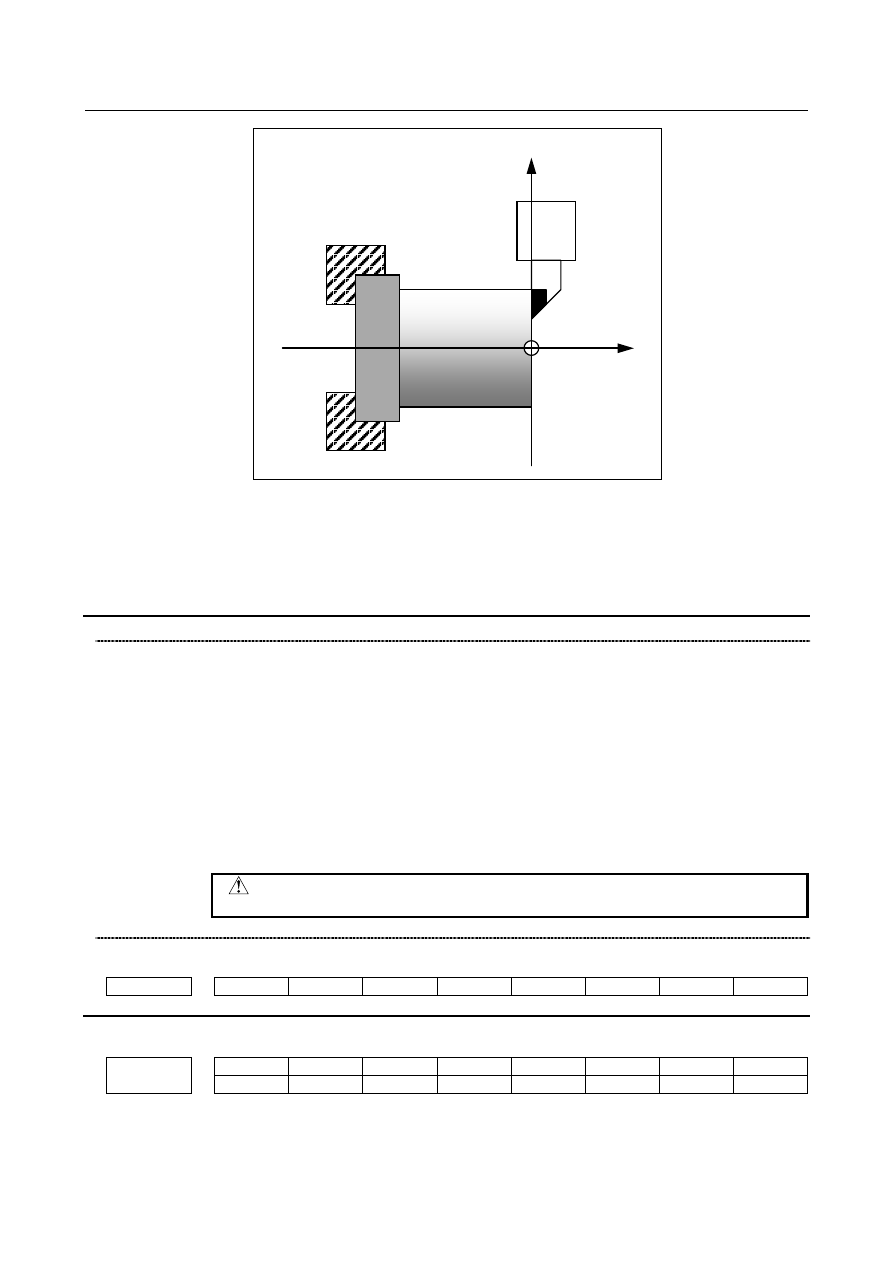
Fig. 1.5.2.6 (a)    Direct input of coordinate system shift 


Relationship between the input of measurement value and the diameter/radius 

specification 

Whether the measured value input and set value use a diameter value or radius value on the setting of bit 

3 (DIAx) of parameter No.1006. 


Signal 

Position record signal PRC <Gn040.6> 

  [Classification]  Input signal 


[Function]  This signal is prepared for the function of direct input of tool offset value measured or 

direct input of coordinate system shift. 


  It is used to store the data on the positions of the tool for tentative cutting in the control 

unit. After measuring the workpiece position, input the measured value by the specified 

manual operation. The difference of the coordinate system actually set and the workpiece 

coordinate system assumed at programming is set in the workpiece coordinate system 

shift value. 


[Operation]  The control unit stores the current position along X and Z axes when the signal turns to 

"1". 


  CAUTION 

  To use this signal, set bit 2 (PRC) of parameter No.5005 to 1. 


Signal address 


#7 

#6 

#5 

#4 

#3 

#2 

#1 

#0 

Gn040 


PRC 


Parameter 


#7 

#6 

#5 

#4 

#3 

#2 

#1 

#0 

1201 


NWS 


[Input type]  Parameter input 


[Data type]  Bit path 


B-64693EN-1/01


1. AXIS CONTROL


- 171 - 


#6  NWS

  The workpiece coordinate system shift amount setting screen is: 

0:  Displayed 

1:  Not displayed 


NOTE 

  When the workpiece coordinate system shift amount setting screen 

is not displayed, a workpiece coordinate system shift amount 

modification using G10P0 cannot be made. If G10P0 is 

commanded, alarm PS0010, "IMPROPER G-CODE" is issued. 


3134 


Data display order of each axis on the workpiece coordinate system setting screen and workpiece 

coordinate system shift amount setting screen 


[Input type]  Parameter input 


[Data type]  Byte axis 

[Valid data range]  0 to Number of controlled axes 

Set the data display order of each axis on the workpiece coordinate system setting screen 

(M series/T series) and workpiece coordinate system shift amount  setting screen (T 

series). 

No data is displayed for an axis with 0 set in this parameter. 


#7 

#6 

#5 

#4 

#3 

#2 

#1 

#0 

3290 


IWZ 

WZO 


IWZ 

WZO 


[Input type]  Parameter input 


[Data type]  Bit path 


#3  WZO

  Setting a workpiece zero point offset value and workpiece shift value (T series) by MDI 

key input is: 

0:  Not disabled. 

1:  Disabled. 


#4  IWZ

  Setting a workpiece zero point offset value or workpiece shift value (T series) by MDI 

key input in the automatic operation activation or halt state is: 

0:  Not disabled. 

1:  Disabled. 


#7 

#6 

#5 

#4 

#3 

#2 

#1 

#0 

5005 


PRC 


[Input type]  Parameter input 


[Data type]  Bit path 


#2  PRC

  For direct input of a tool offset value or workpiece coordinate system shift amount:   

0:  The position record signal PRC <Gn040.6> is not used. 

1:  The position record signal PRC <Gn040.6> is used. 


1. AXIS CONTROL


B-64693EN-1/01


- 172 - 

1.5.2.7 

Each axis workpiece coordinate system preset signals 

Overview 

The each axis workpiece coordinate system preset signals are function for presetting a workpiece 

coordinate system shifted due to manual intervention, a machine lock, etc. to a workpiece coordinate 

system offset from the pre-shift machine zero point by a workpiece origin offset value, using an input 

signal. 

Each axis workpiece coordinate system preset signals become effective by setting bit 6  (WPS) of 

parameter No. 3006 to 1. 

If actual tool length offset need to be considered when workpiece coordinate system preset is done, bit 7 

(WTC) of parameter No. 1205 need to be set to 1. 


Signal 

Each axis workpiece coordinate system preset signals   

WPRST1 to WPRST8 <Gn358> 

  [Classification]  Input signal 


[Function]  These signals are used to preset a workpiece coordinate system shifted due to manual 

intervention, a machine lock, etc. 


[Operation]  By changing the signal for the axis for which to perform a workpiece coordinate system 

preset from “0” to “1”, the workpiece coordinate system preset is performed. This cancels 

the shift amount for the workpiece coordinate system that is due to any of the items below, 

so that the workpiece coordinate system can be preset to a workpiece coordinate system 

preset from the pre-shift machine zero point by the workpiece origin offset value. 


(a)  Manual intervention performed when the manual absolute signal is off 

(b)  Move command executed in the machine lock state 

(c)  Movement by handle interruption 

(d)  Operation using the mirror image function 

(e)  Setting of a local coordinate system with G52 or shift of a workpiece coordinate 

system with G92/G50 (for the T series) 


NOTE 

1  If performing workpiece coordinate system preset with an each axis 

workpiece coordinate system preset signal during automatic 

operation, specify it with the M code set in parameters Nos. 11275 

and 11276 or perform it during a single block stop. 

2  If preset is to be performed with an each axis workpiece coordinate 

system preset signal during automatic operation, the state must be 

that in which all axes on the path including the axis on which to 

perform each axis workpiece coordinate system preset are stopped 

and no commands are in execution. If not all axes are stopped or if 

a command is in execution, alarm PS1820, “ILLEGAL DI SIGNAL 

STATE” is issued. 

B-64693EN-1/01


1. AXIS CONTROL


- 173 - 

NOTE 

3  When an M code for performing each axis workpiece coordinate 

system preset is issued during automatic operation, if the 

corresponding each axis workpiece coordinate system preset signal 

is not set to 1, alarm PS1820 is issued. It is possible to suppress the 

alarm by setting bit 0 (WPA) of parameter No. 11277 to 1. In this 

case, axis workpiece coordinate system preset is not performed. 

4  During a reset (RST<Fn001.1> = “1”), preset with an each axis 

workpiece coordinate system preset signal is disabled. Preset is 

performed at the point the reset is canceled. 

5  During an auxiliary function lock, this function is disabled. 

6  In general, if preset is to be performed with an each axis workpiece 

coordinate system preset signal, the state must be that in which all 

axes on the path including the axis on which to perform each axis 

workpiece coordinate system preset are stopped. However, when 

bit 1 (EAX) of parameter No. 10410 is set to 1 and the axis moves 

by the PMC axis control, it is possible to exclude the axis from this 

condition. That is, the preset can be performed without stopping the 

axis that moves by the PMC axis control. However, when you move 

the axis that moved by the PMC axis control by the NC commands, 

it is necessary to stop the axis, and to reflect the amount of 

movement by PMC axis control to the program coordinate system 

by the manual return to the reference position etc.   

7  Be sure to specify an M code used to turn on each axis workpiece 

coordinate system preset signal in an independent block. 


Each axis workpiece coordinate system preset completion signals   

WPSF1 to WPSF8<Fn358> 

  [Classification]  Output signal 


[Function]  These signals notify the PMC of the each axis workpiece coordinate system preset status.


  [Output cond.]  These signals become “1” in the following case:


When workpiece coordinate system preset is completed with the corresponding each 

axis workpiece coordinate system preset signals. 

They become “0” in the following cases: 

When the corresponding each axis workpiece coordinate system preset signals 

change from “1” to “0”. 

When a reset is performed. 


1. AXIS CONTROL


B-64693EN-1/01


- 174 - 

  -  Timing chart 


M code command (M***) 

Code signal 

(M00 to M31) 

Strobe signal 

(MF) 
Each axis workpiece coordinate 

system preset signal 

(WPRSTn) 

Each axis workpiece coordinate system 

preset completion signal 

(WPSFn) 

Each axis workpiece coordinate system 

preset process 

Completion signal 

(FIN) 


Fig. 1.5.2.7 (a) 


Signal address 


#7 

#6 

#5 

#4 

#3 

#2 

#1 

#0 

Gn358 


WPRST8 

WPRST7 

WPRST6 

WPRST5 

WPRST4 

WPRST3 

WPRST2 

WPRST1 


#7 

#6 

#5 

#4 

#3 

#2 

#1 

#0 

Fn358 


WPSF8 

WPSF7 

WPSF6 

WPSF5 

WPSF4 

WPSF3 

WPSF2 

WPSF1 


Parameter 


#7 

#6 

#5 

#4 

#3 

#2 

#1 

#0 

1205 


WTC 


[Input type]  Parameter input 


[Data type]  Bit path 


#7  WTC

  When workpiece coordinate system preset is done, actual tool length offset is: 

0:  Not considered. 

1:  Considered. 


When this parameter is set 1, it is possible to preset the workpiece coordinate system by 

G-code, MDI operation or the workpiece coordinate system preset signal without 

canceling the tool length compensation modes.   

The compensation vector is kept as the below figure when  the workpiece coordinate 

system preset is done to the coordinate shifted by amount of movement during manual 

intervention. 


B-64693EN-1/01


1. AXIS CONTROL


- 175 - 


Machine zero point 

Amount of movement   

during manual intervention 

Po 

WZo 

Pn 

WZn 

G54 workpiece coordinate 

System before manual   

intervention 

G54 workpiece coordinate   

system after manual 

intervention 

Tool length offset value 

Tool length offset value 


Fig. 1.5.2.7 (b) 


#7 

#6 

#5 

#4 

#3 

#2 

#1 

#0 

3006 


WPS 


[Input type]  Parameter input 


[Data type]  Bit 


#6  WPS

  Each axis workpiece coordinate system preset signal: 

0:  Disabled. 

1:  Enabled. 


#7 

#6 

#5 

#4 

#3 

#2 

#1 

#0 

10410 


EAX 


[Input type]  Parameter input 


[Data type]  Bit axis 


#1  EAX

  When other axis is preset with the workpiece coordinate system preset signal while this 

axis is moving under the PMC axis control: 

0:  The alarm PS1820, “ILLEGAL DI SIGNAL STATE” occurs. 

1:  An alarm doesn’t occur. 


11275 


The top number of M code used to turn on each axis workpiece coordinate system preset signal 


[Input type]  Parameter input 


[Data type]  2-word path 

[Valid data range]  1 to 999999999 

Specify the top number of M code for turning “1” each axis workpiece coordinate system 

preset signal <Gn358.*> during automatic operation. 

When the specified M codes are within the range specified with this  parameter and 

parameter No.11276, each axis workpiece coordinate system preset signal is checked and 

preset workpiece coordinate system for axis that the signal is turned “1”.   

The specified M codes prevent buffering. 


1. AXIS CONTROL


B-64693EN-1/01


- 176 - 

NOTE 

  When each axis workpiece coordinate system preset signals are 

turned “1“ more than two signals by an M code, please turn “1“ the 

signals of all axis at the same timing. If the timing is different, only 

the axis of the first signal turned “1“ is preset.   

If you want to turn “1“ the signals at the different timing, please 

specify M code separately. 


11276 


The number of M code used to turn on each axis workpiece coordinate system preset signal 


[Input type]  Parameter input 


[Data type]  Word path 

[Valid data range]  1 to 999 

Specify  the  number of M code for turning “1”  each axis workpiece coordinate system 

preset signal <Gn358.*> during automatic operation.   

For example, when parameter No.11275 = 100 and parameter No.11276 = 10 are set, 

From M100 to M109 are used for turning “1”  each axis workpiece coordinate system 

preset signal. 

When 0 is set, the number of M code is assumed to be 1. 


NOTE 

  Set only M code that is not used for another function. 

  (M00 to 05, 30, 98, 99, M code used to call the subprogram, etc.) 


#7 

#6 

#5 

#4 

#3 

#2 

#1 

#0 

11277 


WPA 


[Input type]  Parameter input 


[Data type]  Bit path 


#0  WPA

  When an M code for turning on the workpiece coordinate system preset signal for an axis 

is specified, but the signal is not turned on, or an auxiliary function lock is provided: 

0:  An alarm PS1820, “ILLEGAL DI SIGNAL STATE” is issued. 

1:  An alarm is not issued. 


When bit 6 (PGS) of parameter No. 3001 is set to 0 (M, S, T, and B codes are not output 

in the high speed program check mode), if an M code for turning on the workpiece 

coordinate system preset signal for an axis is specified, the system follows the setting of 

this parameter. 


Alarm and message 

Number 

Message 

Description 

PS1820 

ILLEGAL DI SIGNAL 
STATE 

1.  An each axis workpiece coordinate system preset signal was turned on 

in the state in which all axes on the path including the axis on which to 
perform preset with the each axis workpiece coordinate system were 
not stopped or in which a command was in execution. 

2.  When an M code for performing preset with an each axis workpiece 

coordinate system preset signal was specified, the each axis workpiece 
coordinate system preset signal was not turned on. 

3.  The auxiliary function lock is enabled. 
4.  When bit 6 (PGS) of parameter No. 3001 was set to 0 (M, S, T, and B 

codes are not output in the high speed program check mode), an M 
code for turning on an each axis workpiece coordinate system preset 
signal in the high speed program check mode was specified. 

B-64693EN-1/01


1. AXIS CONTROL


- 177 - 


Notes 

NOTE 

  The limitations are the same as those for the workpiece coordinate system preset 

using a program command (G92.1 or G50.3 (for G code system A (T series) or 

using MDI operation. Thus, before performing preset with this function, cancel 

each compensation mode (cutter compensation, tool offset, and tool length 

compensation). Otherwise, the compensation vector will be canceled. If this 

occurs, specify each compensation mode again. For details, refer to the 

OPERATOR’S MANUAL (Common to Lathe System/Machining Center System) 

(B-64694 EN). 


1.5.3 

Local Coordinate System 

Overview 

When a program is created in a workpiece coordinate system, a child workpiece coordinate system can be 

set for easier programming. Such a child coordinate system is referred to as a local coordinate system. 


Format 

G52 

IP

 _;  Setting the local coordinate system 

   : 
G52 

IP

 0 ;  Canceling the local coordinate system 

IP

_  :  Origin of the local coordinate system 


Explanation 

By specifying G52 IP_;, a local coordinate system can be set in all the workpiece coordinate systems 

(G54 to G59). The origin of each local coordinate system is set at the position specified by IP_ in the 

workpiece coordinate system. 

Once a local coordinate system is established, the coordinates in the local coordinate system are used in 

an axis shift command. The local coordinate system can be changed by specifying the G52 command with 

the zero point of a new local coordinate system in the workpiece coordinate system.   

To cancel the local coordinate system and specify the coordinate value in the workpiece coordinate 

system, match the zero point of the local coordinate system with that of the workpiece coordinate system. 


(Local coordinate system) 

(Local coordinate system) 

(Machine coordinate system) 

Machine coordinate system origin 

Reference position 

(G59:  Workpiece coordinate system 6) 

(G54:    Workpiece coordinate system 1) 

G55 

G56 

G57 

G58 

IP_ 

IP_ 


Fig. 1.5.3 (a)    Setting the local coordinate system 


Content      ..     25      26      27      28     ..