FANUC Series 0i-MODEL F Plus. CONNECTION MANUAL (FUNCTION) - page 25
 

  Index      Manuals     FANUC Series 0i-MODEL F Plus. CONNECTION MANUAL (FUNCTION) B-64693EN-1/01


Search            copyright infringement  


Content      ..     23      24      25      26     ..


FANUC Series 0i-MODEL F Plus. CONNECTION MANUAL (FUNCTION) - page 25


1. AXIS CONTROL


B-64693EN-1/01


- 154 - 

- Servo axis 

Diagnosis data No.3740 displays detection unit which is calculated by the following equation. 

Detection unit = Least command increment / CMR 


- Cs contour control axis 

Detection unit of Cs contour control axis is set by bit 0 (CS360M) of parameter No.4005. Diagnosis data 

No.3740 displays the following value. Diagnosis data No.3740 is displayed 0.0 by the hypothetical Cs 

axis (bit 7 (CDMx) of parameter No.3740 = 1). 


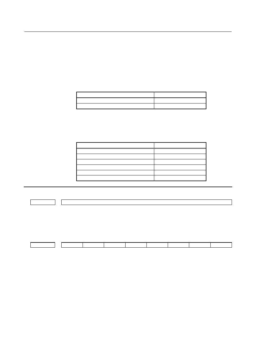
Table 1.4.5 (a)    Detection unit of Cs contour control axis 

Bit 0 (CS360M) of parameter No.4005 

Diagnosis data No.3740 

0.001 

0.0001 


- Spindle positioning axis 

Detection unit of spindle positioning axis is set by gear ratio between spindle and position coder 

(parameter Nos.3721, 3722). Diagnosis data No.3740 displays the following value. 


Table 1.4.5 (b)    Detection unit of spindle positioning axis 

Gear ratio of spindle to position coder 

Diagnosis data No.3740 

1:1 

0.088 (1x360/4096) 

1:2 

0.176 (2x360/4096) 

1:4 

0.352 (4x360/4096) 

1:8 

0.703 (8x360/4096) 

… 

… 

1:N 

(Nx360/4096) 


Diagnosis data 


3740 


Detection unit 


[Data type]  Real axis 


[Unit of data]  mm, inch, deg (machine unit) 

[Valid data range]  0.0 to 99.99 

This diagnosis data displays detection unit. 


#7 

#6 

#5 

#4 

#3 

#2 

#1 

#0 

3741 


DEG 

IN. 

MM 


[Data type]  Bit axis 


#0  MM

  Detection unit is: 

0:  Not mm. 

1:  mm. 


#1   IN.

  Detection unit is: 

0:  Not inch. 

1:  inch. 


#2  DEG

  Detection unit is: 

0:  Not degree. 

1:  degree. 


B-64693EN-1/01


1. AXIS CONTROL


- 155 - 

1.5 

SETTINGS RELATED WITH COORDINATE SYSTEMS 

1.5.1 

Machine Coordinate System 

Overview 

The point that is specific to a machine and serves as the reference of the machine is referred to as the 

machine zero point. A machine tool builder sets a machine zero point for each machine. 

A coordinate system with a machine zero point set as its origin is referred to as a machine coordinate 

system. 

A machine coordinate system is set by performing manual reference position return after power-on. A 

machine coordinate system, once set, remains unchanged until the power is turned off. 


Format 

M


(G90)G53 

IP

 _ P1; 

IP

_  :  Absolute command dimension word 

P1  :  Enables the high-speed G53 function. 


(G90)G53.2 G01 

IP

_

F

_

;   

IP

_  :  Absolute command dimension word 

F_  :  Feedrate 


T


G53 

IP

 _ P1; 

IP

_  :  Absolute command dimension word 

P1  :  Enables the high-speed G53 function. 


G53.2 G01 

IP

_

F

_

;   

IP

_  :  Absolute command dimension word 

F_  :  Feedrate 


Explanation 

  -  Selecting a machine coordinate system (G53) 

When a command is specified the position on a machine coordinate system, the tool moves to the position 

by rapid traverse. G53, which is used to select a machine coordinate system, is a one-shot G code; that is, 

it is valid only in the block in which it is specified on a machine coordinate system. Specify an absolute 

command for G53. When an incremental command is specified, the G53 command is ignored. When the 

tool is to be moved to a machine-specific position such as a tool change position, program the movement 

in a machine coordinate system based on G53. 


  -  High-speed G53 function 

The high-speed G53 function enables the rapid traverse block overlap function between the machine 

coordinate system selection command (G53) block and positioning (rapid traverse) command (G00) block, 

which allows the next rapid traverse command (G00) to be executed without decelerating and stopping 

the tool at the end of the machine coordinate system selection command (G53).  This function enables 

high-speed positioning even when the machine coordinate system selection command (G53) is used.


The high-speed G53 function is enabled by specifying P1 in the G53 block.


1. AXIS CONTROL


B-64693EN-1/01


- 156 - 

  -  Selecting a machine coordinate system with feedrate (G53.2) 

Positioning of machine coordinate system at a feed rate is available with the command of G53.2. The feed 

rate can be used in the modal of G01. 


NOTE 

  The selecting a machine coordinate system with feedrate (G53.2) is an option. 

  To use this function, an option of the selecting a machine coordinate system with 

feedrate is required. 


G53.2 is one shot G code. Moreover, the tool offset value is temporarily canceled by G53.2 command like 

G53. 

As for the time constant, a usual feed rate are used. At the point of G53.2 command, the axis decelerates 

to a stop once like G53 command.   

Feed per minute, feed per revolution, and inverse time feed of G codes of 05 group are available. 

When group 01 G-code except G00/G01 is commanded with G53.2, the alarm PS5372,  “IMPROPER 

MODAL G-CODE” is generated. And, when G53.2 is commanded while group 01 Modal G-code is the 

one except G00/G01, the alarm PS5372 is generated. 


Limitation 

  -  Cancel of the compensation function 

When the G53 command is specified, cancel the compensation functions such as the cutter compensation, 

tool length offset, tool-nose radius compensation, and tool offset. 


  -  G53 specification immediately after power-on 

Since the machine coordinate system must be set before the G53 command is specified, at least one 

manual reference position return or automatic reference position return by the G28 command must be 

performed after the power is turned on. This is not necessary when an absolute-position detector is 

attached. 


Specification in the same block 

M


Commands G50/G51, G50.1/G51.1, and G68/G69 cannot be specified in the same block where the G53 

command is specified. 


T


Commands G50/G51 (except for G code system A), G50.1/G51.1, and G68.1/G69.1 cannot be specified 

in the same block where the G53 command is specified. 


Reference 

  -  Setting a machine coordinate system 

When manual reference position return is performed after power-on, a machine coordinate system is set 

so that the reference position is at the coordinate values of (

a

b

) set using parameter No.1240. 

B-64693EN-1/01


1. AXIS CONTROL


- 157 - 

b

Reference position

Machine coordinate system

Machine zero point

a


Fig. 1.5.1 (a) 


Example (selecting a machine coordinate system with feedrate) 

N1 G90 G01 ; 


N2 G53.2 X50.0 Y100.0 F1000 ; Absolute command with feedrate F1000 

N3 G53.2 X150.0 F500 ; 

Absolute command with feedrate F500 


Fig. 1.5.1 (b) 


Parameter 

1240 


Coordinate value of the reference position in the machine coordinate system 


NOTE 

  When this parameter is set, the power must be turned off before 

operation is continued. 


[Input type]  Parameter input 


[Data type]  Real axis 


[Unit of data]  mm, inch, deg (machine unit) 

[Min. unit of data] Depend on the increment system of the applied axis 

[Valid data range]  9 digit of minimum unit of data (refer to standard parameter setting table (A)) 

(When the increment system is IS-B, -999999.999 to +999999.999) 

Set the coordinate values of the reference position in the machine coordinate system. 


Alarm and message 

Number 

Message 

Description 

PS5372  IMPROPER MODAL G-CODE (G53.2) 

In the G53.2 block, a G code in group 01 other than G00 or 
G01 is specified. Alternatively, G53.2 is specified when the 
modal G code in group 01 is other than G00 or G01. 


Y axis 


100 


50            150         X axis 

Temporarily decelerates and stops. 

1. AXIS CONTROL


B-64693EN-1/01


- 158 - 

Reference item 

Manual name 

Item name 

OPERATOR’S MANUAL (B-64694EN) 

Machine coordinate system 


1.5.2 

Workpiece Coordinate System/Addition of Workpiece 

Coordinate System Pair 

Overview 

A coordinate system used for machining a workpiece is referred to as a workpiece coordinate system. A 

workpiece coordinate system is to be set with the CNC beforehand (setting a workpiece coordinate 

system). 

A machining program sets a workpiece coordinate system (selecting a workpiece coordinate system). 

A set workpiece coordinate system can be changed by shifting its origin (changing a workpiece 

coordinate system).   


1.5.2.1 

Workpiece coordinate system 


NOTE 

  To use the workpiece coordinate system, set 0 in bit 0 (NWZ) of parameter 

No.8136. 


  -  Setting a workpiece coordinate system 

A workpiece coordinate system can be set using one of three methods: 

(1)  Method using a workpiece coordinate system setting G code 


A workpiece coordinate system is set by specifying a value in the program after a workpiece 

coordinate system setting G code. 

(2)  Automatic setting 


If bit 0 (ZPR) of parameter No. 1201 is set to 1, a workpiece coordinate system is automatically set 

when manual reference position return is performed. 


This function is, however, disabled when the workpiece coordinate system is being used. 

(3)  Method using a workpiece coordinate system selection G code 


Six workpiece coordinate systems can be set beforehand using the MDI unit. Program commands 

G54 to G59 can be used to select the work axis to be used. 

When using an absolute command, establish the workpiece coordinate system in any of the above ways. 


  CAUTION 

  The established workpiece coordinate system depends on diameter 

programming or radius programming. 


  -  Selecting a workpiece coordinate system 

The user can choose from set workpiece coordinate systems as described below. 

(1)  Selecting a workpiece coordinate system set by workpiece coordinate system setting G code (G92, 

G50) or automatic workpiece coordinate system setting 


Once a workpiece coordinate system is selected, absolute commands work with the workpiece 

coordinate system. 

(2)  Choosing from six workpiece coordinate systems set using the MDI unit 


By specifying a G code from G54 to G59, one of the workpiece coordinate systems 1 to 6 can be 

selected. 


G54 ..... Workpiece coordinate system 1 

G55 ..... Workpiece coordinate system 2 


G56 ..... Workpiece coordinate system 3 

G57 ..... Workpiece coordinate system 4 


G58 ..... Workpiece coordinate system 5 

G59 ..... Workpiece coordinate system 6 

B-64693EN-1/01


1. AXIS CONTROL


- 159 - 

Workpiece coordinate systems  1 to 6 are established after reference position return after the power is 

turned on. When the power is turned on, G54 coordinate system is selected as default. 


When bit 2 (G92) of parameter No. 1202 is set to 1, executing the G code command for coordinate system 

setting (G92 <M series>, G50 <Tseries> (G92 with G code system B/C for T series)) results in the issue 

of alarm PS0010,  “IMPROPER G-CODE”. This is designed to prevent the user from confusing 

coordinate systems. 


  CAUTION 

  The set workpiece zero point offset value depends on diameter programming or 

radius programming. 


  -  Changing workpiece coordinate system 

The six workpiece coordinate systems specified with G54 to G59 can be changed by changing an external 

workpiece zero point offset value or workpiece zero point offset value.   

Three methods are available to change an external workpiece zero point offset value or workpiece zero 

point offset value. 

(1)  Inputting from the MDI unit 

(2)  Programming (using a programmable data input G code or a workpiece coordinate system setting G 

code) 

(3)  Using the external data input function 


An external workpiece zero point offset value can be changed by input signal to CNC. Refer to 

machine tool builder's manual for details. 


Workpiece 

coordinate system 1 

(G54) 

Workpiece 

coordinate system 2 

(G55) 

Workpiece coordinate 

system 3 

(G56) 

Workpiece coordinate 

system 4 

(G57) 

Workpiece coordinate 

system 5 
(G58) 

Workpiece coordinate 

system 6 

(G59) 

ZOFS2 

ZOFS3 

ZOFS4 

ZOFS5 

ZOFS1 

ZOFS6 

Machine zero point 

EXOFS :External workpiece zero point offset value 
ZOFS1 to ZOFS6 : Workpiece zero point offset value 

EXOFS 


Fig. 1.5.2.1 (a) Changing an external workpiece zero point offset value or workpiece zero point offset value 


Format 

  -  Changing by inputting programmable data 

G10 L2 Pp 

IP

_; 

p=0 

:  External workpiece zero point offset value 

p=1 to 6 :  Workpiece zero point offset value correspond to workpiece coordinate system 1 to 6 

IP

_:  For an absolute command, workpiece zero point offset for each axis. 


For an incremental command, value to be added to the set workpiece zero point offset for each axis (the 
result of addition becomes the new workpiece zero point offset). 

1. AXIS CONTROL


B-64693EN-1/01


- 160 - 

Changing by setting a workpiece coordinate system 

M


G92 

IP

_;


T


G50 

IP

_;


Explanation 

  -  Changing by inputting programmable data 

By specifying a programmable data input G code, the workpiece zero point offset value can be changed 

for each workpiece coordinate system. 


  -  Changing by setting a workpiece coordinate system 

By specifying a workpiece coordinate system setting G code, the workpiece coordinate system (selected 

with a code from G54 to G59) is shifted to set a new workpiece coordinate system so that the current tool 

position matches the specified coordinates (IP_). 

Then, the amount of coordinate system shift is added to all the workpiece zero point offset values. This 

means that all the workpiece coordinate systems are shifted by the same amount. 


  CAUTION 

  When a coordinate system is set with G code command for workpiece coordinate 

system setting after an external workpiece zero point offset value is set, the 

coordinate system is not affected by the external workpiece zero point offset 

value. When G92X100.0Z80.0; is specified, for example, the coordinate system 

having its current tool reference position at X = 100.0 and Z = 80.0 is set. 


T


If IP is an incremental command value, the work coordinate system is defined so that the current tool 

position coincides with the result of adding the specified incremental value to the coordinates of the 

previous tool position. (Coordinate system shift) 

When bit 0 (WAB) of parameter No. 11279 is set to 1, the setting of the workpiece coordinate system is 

executed with absolute value even if the work coordinate system setting (G92) is commanded during the 

incremental mode (G91) in the G-code system B/C of the lathe system. 


Notes 

  -  Manual reference position return 

When the manual reference position return is performed, the value of the workpiece coordinate system set 

by G code (G92, or G50 for the lathe system G-code system A) is cleared to 0. And when the automatic 

reference position return (G28) is performed,  this workpiece coordinate system is not cleared to 0 but 

stored. 


Parameter 


#7 

#6 

#5 

#4 

#3 

#2 

#1 

#0 

11279 


WAB 


[Input type]  Parameter input 


[Data type]  Bit 


B-64693EN-1/01


1. AXIS CONTROL


- 161 - 


#0  WAB

  When the incremental mode (G91) is selected in the G-code system B/C of the lathe 

system, if the setting of the workpiece coordinate system (G92) is commanded, the setting 

of the workpiece coordinate system is executed with: 

0:  Incremental value. 

1:  Absolute value. 


1.5.2.2 

Workpiece coordinate system preset 


NOTE 

  To use the workpiece coordinate system preset function, set 0 in bit 1 (NWC) of 

parameter No. 8136. 


Explanation 

In reset state, execute Manual reference position return, a workpiece coordinate system is shifted by the 

workpiece zero point offset value from the machine coordinate system zero point. Suppose that the 

manual reference position return operation is performed when a workpiece coordinate system is selected 

with G54. In this case, a workpiece coordinate system is automatically set which has its zero point 

displaced from the machine zero point by the G54 workpiece zero point offset value; the distance from 

the zero point of the workpiece coordinate system to the reference position represents the current position 

in the workpiece coordinate system. 


Reference position 

G54 workpiece coordinate system 

Workpiece zero point 

Manual reference position return 

Machine zero point 

G54 workpiece 

zero point offset 

value 


Fig. 1.5.2.2 (a)   


If an absolute position detector is provided, the workpiece coordinate system automatically set at 

power-up has its zero point displaced from the machine zero point by the G54 workpiece zero point offset 

value. The machine position at the time of power-up is read from the absolute position detector and the 

current position in the workpiece coordinate system is set by subtracting the G54 workpiece zero point 

offset value from this machine position. The workpiece coordinate system set by these operations is 

shifted from the machine coordinate system using the commands and operations listed below. 


(a)  Manual intervention performed when the manual absolute signal is off 

(b)  Move command executed in the machine lock state 

(c)  Movement by handle interrupt 

(d)  Operation using the mirror image function   

(e)  Shifting the workpiece coordinate system by setting the local coordinate system or workpiece 

coordinate system 


In the case of (a) above, the workpiece coordinate system is shifted by the amount of movement during 

manual intervention. 


Content      ..     23      24      25      26     ..