FANUC Series 0i-MODEL F Plus. CONNECTION MANUAL (FUNCTION) - page 26
 

  Index      Manuals     FANUC Series 0i-MODEL F Plus. CONNECTION MANUAL (FUNCTION) B-64693EN-1/01


Search            copyright infringement  


Content      ..     24      25      26      27     ..


FANUC Series 0i-MODEL F Plus. CONNECTION MANUAL (FUNCTION) - page 26


1. AXIS CONTROL


B-64693EN-1/01


- 162 - 


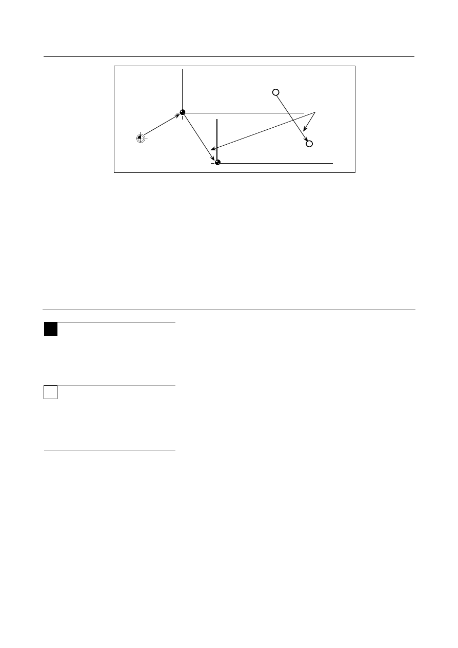
WZn

-


Machine zero point   

Workpiece zero 

point offset value 

Wzo 

G54 workpiece 

coordinate system before 

manual intervention 

G54 workpiece coordinate 

system after manual 

intervention 

Po 

Pn 

Amount of 

movement during 

manual intervention 


Fig.1.5.2.2 (b) 


In the operation above, like execute Manual reference position return, a workpiece coordinate system 

once shifted can be preset using G code specification (G92.1/G50.3 (G code system A (T series))) or MDI 

operation (Refer to OPERATOR’S MANUAL (Common to Lathe System / Machining Center System) 

(B-64694EN) “Workpiece Coordinate System Preset” in “SETTING AND DISPLAYING DATA”) to a 

workpiece coordinate system displaced by a workpiece zero point offset value from the machine zero 

point.   

Bit 3 (PPD) of parameter No. 3104 specifies whether to preset relative coordinates as well as absolute 

coordinates. 

When no workpiece coordinate system option (G54 to G59) is not provided (1 is set in bit 0 (NWZ) of 

parameter No. 8136), the workpiece coordinate system is preset to the coordinate system with its zero 

point placed at the reference position. 


Limitation 

M


  -  Cutter compensation, tool length compensation, tool offset 

When using the workpiece coordinate system preset function, cancel compensation modes: cutter 

compensation, tool length compensation, and tool offset. If the function is executed without cancelling 

these modes, compensation vectors are cancelled. 


T


  -  Tool-nose radius compensation, tool offset 

When using the workpiece coordinate system preset function, cancel compensation modes: tool-nose 

radius compensation and tool offset. If the function is executed without cancelling these modes, 

compensation vectors are cancelled. 


  -  Program restart 

The workpiece coordinate system preset function is not executed during program restart.


  -  Prohibited modes 

Do not use the workpiece coordinate system preset function when the scaling, coordinate system rotation, 

programmable mirror image, or drawing copy mode is set.


B-64693EN-1/01


1. AXIS CONTROL


- 163 - 

1.5.2.3 

Adding workpiece coordinate systems (G54.1 or G54) 

M


Besides the six workpiece coordinate systems (standard workpiece coordinate systems) selectable with 

G54 to G59, 48 or 300 additional workpiece coordinate systems (additional workpiece coordinate 

systems) can be used. 


NOTE 

1  To use the additional workpiece coordinate systems (48 pairs), set 0 in bit 0 

(NWZ) of parameter No. 8136 and 0 in bit 2 (NWN) of parameter No. 8136. 

2  The additional workpiece coordinate systems (300 pairs) is an option. To use this 

function, an option of the additional workpiece coordinate systems (300 pairs) is 

required. 


Explanation 

  -  Selecting the additional workpiece coordinate systems 

When a P code is specified together with G54.1 (G54), the corresponding coordinate system is selected 

from the additional workpiece coordinate systems (1 to 48 or 1 to 300). 

A workpiece coordinate system, once selected, is valid until another workpiece coordinate system is 

selected. Standard workpiece coordinate system 1 (selectable with G54) is selected at power-on. 

G54.1 P1 ......... Additional workpiece coordinate system 1 

G54.1 P2 ......... Additional workpiece coordinate system 2 

    : 

G54.1 P48 ....... Additional workpiece coordinate system 48 

    : 

G54.1 P300 ..... Additional workpiece coordinate system 300 


As with the standard workpiece coordinate systems, the following operations can  be performed for a 

workpiece zero point offset in an additional workpiece coordinate system: 

(1)  The workpiece zero point offset value setting screen can be used to display and set a workpiece zero 

point offset value. 

(2)  The G10 function enables a workpiece zero point offset value to be set by programming. 

(3)  A custom macro allows a workpiece zero point offset value to be handled as a system variable. 

(4)  Workpiece zero point offset data can be entered or output as external data. 

(5)  The PMC window function enables workpiece zero point offset data to be read as program command 

modal data. 


  -  Setting the workpiece zero point offset value in the additional coordinate 

systems (G10) 

When a workpiece zero point offset value is specified using an absolute value, the specified value is the 

new offset value. When it is specified using an incremental value, the specified value is added to the 

current offset value to obtain a new offset value. 


Limitation 

  -  Specifying P codes 

A P code must be specified after G54.1 (G54). If G54.1 is not followed by a P code in the same block, 

additional workpiece coordinate system 1 (G54.1P1) is assumed. 

If a value not within the specifiable range is specified in a P code, an alarm PS0030, “ILLEGAL OFFSET 

NUMBER” is issued. 

P codes other than workpiece offset numbers cannot be specified in a G54.1 (G54) block. 

Example 1)  G54.1G04P1000; 

Example 2)  G54.1M98P48; 


1. AXIS CONTROL


B-64693EN-1/01


- 164 - 

1.5.2.4 

Automatic coordinate system setting 

When bit 0 (ZPR) of parameter No. 1201 for automatic coordinate system setting is 1, a coordinate 

system is automatically determined when manual reference position return is performed. 

Once 

a

b

, and 

γ

 are set with parameter No. 1250, a workpiece coordinate system is set upon reference 

position return so that the base point on the tool holder or the tip of the basic tool is positioned at X = 

a

Y = 

b

, and Z = 

γ

This processing occurs as if the following are specified at the reference position: 

Note that this cannot be used when the workpiece coordinate system is provided (when 0 is set in bit 0 

(NWZ) of parameter No. 8136). 


M


     G92 X

a

 Y

b

 Z

γ

 ; 


T


     G50 X

a

 Z

γ

 ; 


When the setting of a workpiece coordinate system shift amount is other than 0, a workpiece coordinate 

system shifted by the amount is set. 


1.5.2.5 

Workpiece coordinate system shift 

T


Explanation 

When the coordinate system actually set by the G50 command or the automatic system setting deviates 

from the programmed workpiece coordinate system, the set coordinate system can be shifted.  Set the 

desired shift amount in the work coordinate system shift memory. 


Fig. 1.5.2.5 (a) Workpiece coordinate system shift 


Format 

  -  Changing the workpiece coordinate system shift amount 

G10 P0 

IP

_; 

IP


:  Settings of an axis address and a workpiece coordinate system shift amount 


B-64693EN-1/01


1. AXIS CONTROL


- 165 - 

  CAUTION 

1  A single block can contain a combination of X, Y, Z, C, U, V, W, and H (in G-code 

system A). In this case, if commands are specified for the same axis, whichever 

appears later becomes valid. 

2  Be sure not to specify other G codes for the same block. When specified, only 

modal information is updated. 

3  Be sure not to specify any auxiliary functions / spindle speed functions / tool 

functions or 2nd auxiliary functions for the same block. When specified, alarm 

PS1144 "G10 FORMAT ERROR" is issued. 

4  When it commanded with bit 6 (NWS) of parameter No. 1201 is set to 1, alarm 

PS0010, "IMPROPER G-CODE" is issued. 


Limitation 

  -  Shift amount and coordinate system setting command 

Specifying a coordinate system setting command (G50 or G92) invalidates the shift amount that has 

already been set. 

Example) 


When G50X100.0Z80.0; is specified, a coordinate system is set so that the current base position of 

the tool is at X =100.0 and Z = 80.0, regardless of which value has been set for the workpiece 

coordinate system shift amount. 


  -  Shift amount and coordinate system setting 

After a shift amount is set, when automatic coordinate system setting is performed upon manual reference 

position return, the set coordinate system is immediately shifted by the set amount. 


  -  Diameter and radius values 

The workpiece coordinate system shift amount depends on diameter programming or radius 

programming. 


Example) 


Although the base point should be positioned at X = 

φ

120.0 (diameter value) and Z = 70.0 from the 

workpiece zero point, the actual position is at X = 

φ

121.0 and Z = 69.0 from the zero point. Set a 

shift amount as shown below: 


X=1.0, Z=-1.0 


69.0 

Start point = base 

point 

φ

121.0


Fig. 1.5.2.5 (b) 


1. AXIS CONTROL


B-64693EN-1/01


- 166 - 

Parameter 


#7 

#6 

#5 

#4 

#3 

#2 

#1 

#0 

1201 


WZR 

NWS 


ZPR 


WZR 


ZPR 


[Input type]  Parameter input 


[Data type]  Bit path 


#0  ZPR

  Automatic setting of a coordinate system when the manual reference position return is 

performed 

0:  Not set automatically 

1:  Set automatically 


NOTE 

  ZPR is valid while a workpiece coordinate system function is not 

provided (bit 0 (NWZ) of parameter No.8136 is 1). If a workpiece 

coordinate system function is provided, making a manual reference 

position return always causes the workpiece coordinate system to 

be established on the basis of the workpiece zero point offset 

(parameters Nos. 1220 to 1226), irrespective of this parameter 

setting. 


#6  NWS

  The workpiece coordinate system shift amount setting screen is: 

0:  Displayed 

1:  Not displayed 


NOTE 

  When workpiece coordinate system shift amount setting screen is 

not displayed, a workpiece coordinate system shift amount 

modification using G10P0 cannot be made. If G10P0 is 

commanded, alarm PS0010, "IMPROPER G-CODE" is issued. 


#7  WZR

  If the CNC  is reset by the reset key on the  MDI unit, external  reset  signal, reset and 

rewind signal, or emergency stop signal when bit 6 (CLR) of parameter No. 3402 is set to 

0, the G code of group number 14 (workpiece coordinate system) is: 

0:  Placed in the reset state (not returned to G54). 

1:  Placed in the cleared state (returned to G54). 


NOTE 

1  When the 3-dimensional conversion mode is set, and bit 2 (D3R) of 

parameter No. 5400 is set to 1, the G code is placed in the reset 

state, regardless of the setting of this parameter. 

2  When bit 6 (CLR) of parameter No. 3402 is set to 1, whether to 

place the G code in the reset state depends on bit 6 (C14) of 

parameter No. 3407. 


#7 

#6 

#5 

#4 

#3 

#2 

#1 

#0 

1202 


G92 

EWS 

EWD 


G92 


EWD 


[Input type]  Parameter input 


[Data type]  Bit path 

B-64693EN-1/01


1. AXIS CONTROL


- 167 - 


#0  EWD

  The shift direction of the workpiece coordinate system is: 

0:  The direction specified by the external workpiece zero point offset value 

1:  In the opposite direction to that specified by the external workpiece zero point offset 

value 


#1  EWS

  The external workpiece zero point offset is made: 

0:  Valid 

1:  Invalid 


NOTE 

  When the external workpiece zero point offset is made invalid, the 

following operation results: 

1  As the external workpiece zero point offset on the workpiece zero 

point offset setting screen, a workpiece coordinate system shift 

amount is displayed. 

2  Data keyed through the MDI unit for the workpiece coordinate 

system shift amount and external workpiece zero point offset is 

loaded into the memory for the workpiece coordinate system shift 

amount. 

3  A write to or read from the workpiece coordinate system shift 

amount and external workpiece zero point offset with a macro 

variable is performed using the respective memory. 

4  A write to or read from the workpiece coordinate system shift 

amount and external workpiece zero point offset with the window 

function is performed using the respective memory. 


#2  G92

  When the workpiece coordinate system is used (when bit 0 (NWZ) of parameter No. 8136 

is 0), if the G command for setting a coordinate system (G92 for M series, G50 for T 

series (or the G92 command in G command system B or C)) is specified,   

0:  G command is executed and no alarm is issued. 

1:  G  command is not executed and an  alarm  PS0010,  “IMPROPER G-CODE” is 

issued. 


1220 


External workpiece zero point offset value in each axis 


[Input type]  Setting input 


[Data type]  Real axis 


[Unit of data]  mm, inch, deg (input unit) 

[Min. unit of data] Depend on the increment system of the applied axis 

[Valid data range]  9 digit of minimum unit of data (refer to standard parameter setting table (A)) 

(When the increment system is IS-B, -999999.999 to +999999.999) 

This is one of the parameters that give the position of the zero point of workpiece 

coordinate system (G54 to G59). It gives an offset of the workpiece zero point common 

to all workpiece coordinate systems. In general, the offset varies depending on the 

workpiece coordinate systems. The value can be set from the PMC using the external data 

input function. 


1221 


Workpiece zero point offset value in workpiece coordinate system 1 (G54) 


1222 


Workpiece zero point offset value in workpiece coordinate system 2(G55) 


1223 


Workpiece zero point offset value in workpiece coordinate system 3(G56) 


1224 


Workpiece zero point offset value in workpiece coordinate system 4 (G57) 


1. AXIS CONTROL


B-64693EN-1/01


- 168 - 

1225 


Workpiece zero point offset value in workpiece coordinate system 5 (G58) 


1226 


Workpiece zero point offset value in workpiece coordinate system 6 (G59) 


[Input type]  Setting input 


[Data type]  Real axis 


[Unit of data]  mm, inch, deg (input unit) 

[Min. unit of data] Depend on the increment system of the applied axis 

[Valid data range]  9 digit of minimum unit of data (refer to standard parameter setting table (A)) 

(When the increment system is IS-B, -999999.999 to +999999.999) 

The workpiece zero point offset values in workpiece coordinate systems 1 to 6 (G54 to 

G59) are set.   


1250 


Coordinate system of the reference position used when automatic coordinate system setting is 

performed 


[Input type]  Parameter input 


[Data type]  Real axis 


[Unit of data]  mm, inch, deg (input unit) 

[Min. unit of data] Depend on the increment system of the applied axis 

[Valid data range]  9 digit of minimum unit of data (refer to standard parameter setting table (A)) 

(When the increment system is IS-B, -999999.999 to +999999.999) 

Set the coordinate system of the reference position on each axis to be used for setting a 

coordinate system automatically. 


#7 

#6 

#5 

#4 

#3 

#2 

#1 

#0 

3104 


PPD 


[Input type]  Parameter input 


[Data type]  Bit path 


#3  PPD

  Relative position display when a coordinate system is set 

0:  Not preset 

1:  Preset 


NOTE 

  If any of the following is executed when PPD is set to 1, the relative 

position display is preset to the same value as the absolute position 

display: 

(1)  Manual reference position return 

(2)  Coordinate system setting based on G92 (G50 for G code 

system A on the lathe system) 

(3)  Workpiece coordinate system presetting based on G92.1 

(G50.3 for G code system A on the lathe system) 

(4)  When a T code for the lathe system is specified. 


#7 

#6 

#5 

#4 

#3 

#2 

#1 

#0 

3290 


IWZ 

WZO 


[Input type]  Parameter input 


[Data type]  Bit path 


#3  WZO

  Setting a workpiece zero point offset value and workpiece shift value (T series) by MDI 

key input is: 

0:  Not disabled. 

B-64693EN-1/01


1. AXIS CONTROL


- 169 - 

1:  Disabled. 


#4  IWZ

  Setting a workpiece zero point offset value or workpiece shift value (T series) by MDI 

key input in the automatic operation activation or halt state is: 

0:  Not disabled. 

1:  Disabled. 


1.5.2.6 

Direct input of coordinate system shift 

T


Explanation 

If the tool position assumed at programming  is  inputted  when  the coordinate system actually set is 

different from the workpiece coordinate system assumed at programming, shift length of the coordinate 

system actually set and the workpiece coordinate system assumed at programming is set in the workpiece 

coordinate system shift value. 

The procedure leading up to inputting coordinate system position depend on the setting made for bit 2 

(PRC) of parameter No.5005. 

The procedure in which the coordinate system position of workpiece end face is specified is as follows. 


When bit 2 (PRC) of parameter No.5005 is set to 0 

1  Cut the workpiece end face tentatively. 
2  Display the workpiece coordinate system shift amount setting screen with touching  tool to the 

workpiece end face. 

3  Move the cursor to Z axis of MEASUREMENT. 
4  Input the workpiece end face position on workpiece coordinate system assumed at programming and 

press soft key [INPUT]. 


When bit 2 (PRC) of parameter No.5005 is set to 1 

1  Cut the workpiece end face tentatively. 
2  Set the position record signal PRC to "1" with touching tool to the workpiece end face. 
3  Remove a tool from the workpiece end face. 
4  Display the workpiece coordinate system shift amount setting screen. 
5  Move the cursor to Z axis of MEASUREMENT. 
6  Input the workpiece end face position on workpiece coordinate system assumed at programming and 

press soft key [INPUT]. 


Content      ..     24      25      26      27     ..