FANUC Series 0i-MODEL F Plus. CONNECTION MANUAL (FUNCTION) - page 22
 

  Index      Manuals     FANUC Series 0i-MODEL F Plus. CONNECTION MANUAL (FUNCTION) B-64693EN-1/01


Search            copyright infringement  


Content      ..     20      21      22      23     ..


FANUC Series 0i-MODEL F Plus. CONNECTION MANUAL (FUNCTION) - page 22


1. AXIS CONTROL


B-64693EN-1/01


- 130 - 

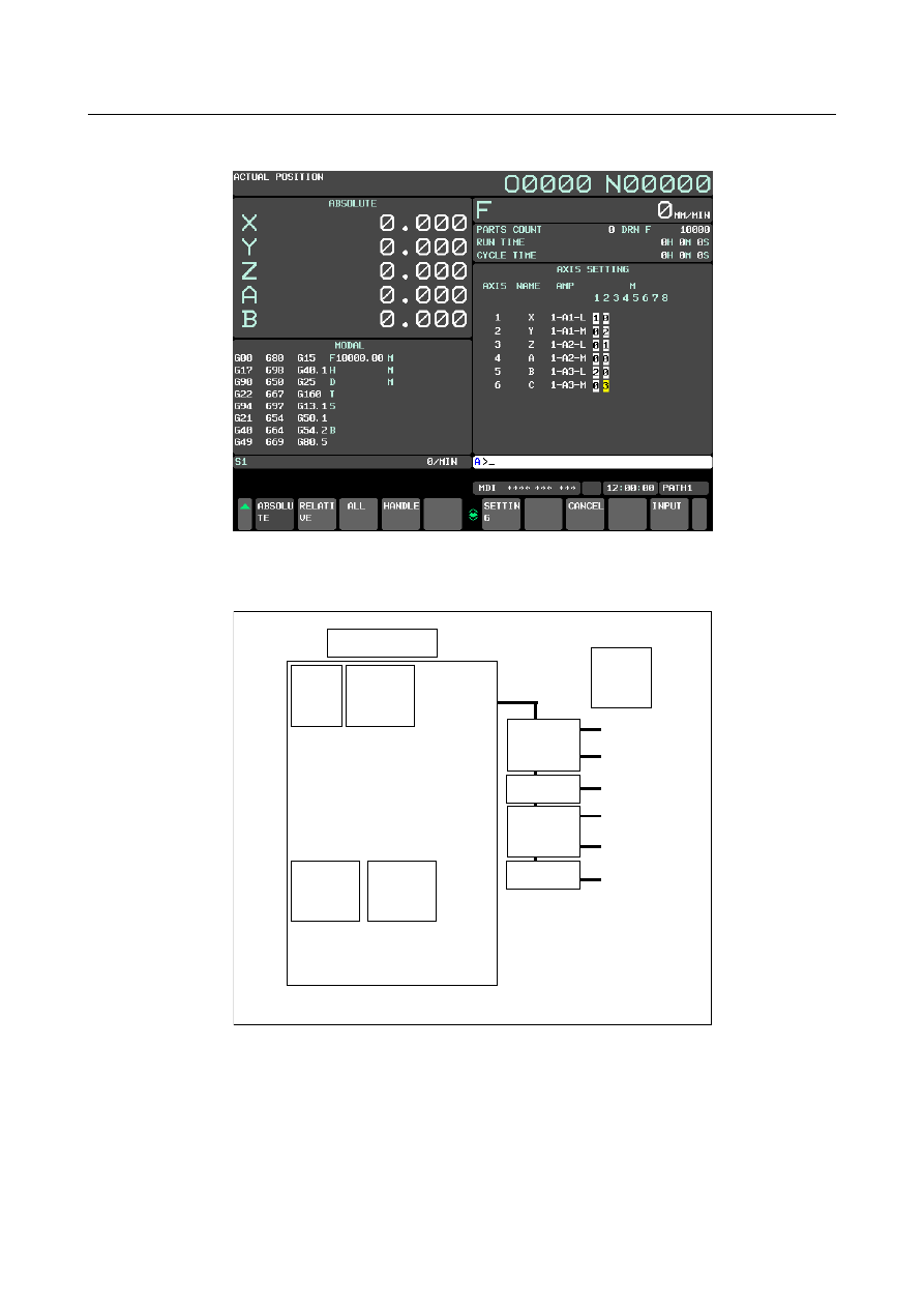
<1>  On the axis setting screen, enter 1 in M1 for the X-axis, 2 in M2 for the Y-axis, 1 in M2 for the 

Z-axis, 2 in M1 for the B-axis, and 3 in M2 for the C-axis. 


<2>  Press the soft key [SETTING] to perform FSSB automatic setting. 


  -  Example 3    Cs contour control 


X


Y


Z


B


Axis


1


X


2


Y


3


Z


4


A  (Cs contour 

controlled axis)


5


B


CNC


SV(2 axes)


SV(2 axes)


SV: Servo amplifier 

SP: Spindle amplifier


Controlled 

axis 

number 

Program 

axis name 

No.1020


SP


SP


S1


S2


Spindle 

number


1


2


Spindle 

name


S1 (Cs contour 

controlled axis)


S2


Fig. 1.4.3.2 (g) Setting example (Cs contour control) 


B-64693EN-1/01


1. AXIS CONTROL


- 131 - 

<1>  On the servo amplifier setting screen, enter 1, 2, 3, and 5 for AXIS. 


<2>  On the spindle amplifier setting screen, enter 1 and 2 for SP NUM. 


1. AXIS CONTROL


B-64693EN-1/01


- 132 - 

<3>  On the axis setting screen, enter 1 in Cs for the A-axis. 


<4>  Press the soft key [SETTING] to perform FSSB automatic setting. 


  -  Example 4  Tandem control 


X


A


Y


B


Z


C


Axis


1


X (tandem master)


2


Y


3


Z


4


A (tandem slave)


5


B


6


C


CNC


SV(2 axes)


SV(2 axes)


Controlled 

axis 

number 

Program 

axis name 

No.1020


SV(2 axes)


SV: Servo amplifier


Fig. 1.4.3.2 (h) Setting example (tandem control) 


B-64693EN-1/01


1. AXIS CONTROL


- 133 - 

<1>  On the servo amplifier setting screen, enter 1, 4, 2, 5, 3, and 6 for AXIS. 


<2>  On the axis setting screen, enter 1 in M/S for the X-axis and 2 in M/S for the A-axis. 


<3>  Press the soft key [SETTING] to perform FSSB automatic setting. 


1. AXIS CONTROL


B-64693EN-1/01


- 134 - 

  -  Example 5    Electronic gear box 


Axis 


X (EGB slave) 

B (EGB dummy) 

Controlled 

axis 

number 

Program axis 

name 

No.1020


CNC 

SV(2 axes) 

SV(2 axes) 

SV: Servo amplifier


Fig. 1.4.3.2 (i) Setting example (electronic gear box) 


<1>  For the X- and B-axes, set bit 0 (SYN) of parameter No. 2011 to 1. 

<2>  On the servo amplifier setting screen, enter 1, 2, 3, and 4 for AXIS. 


B-64693EN-1/01


1. AXIS CONTROL


- 135 - 

<3>  On the axis setting screen, enter 1 in M/S for the X-axis and 2 in M/S for the B-axis. 


<4>  Press the soft key [SETTING] to perform FSSB automatic setting. 


Parameter 

1023 


Number of the servo axis for each axis 


NOTE 

  When this parameter is set, the power must be turned off before 

operation is continued. 


[Input type]  Parameter input 


[Data type]  Byte axis 

[Valid data range]  0 to 78 

This parameter associates each control axis with a specific servo axis. Usually, set the 

same number as a controlled axis number and its corresponding servo axis number. 

The control axis number is the order number that is used for setting the axis-type 

parameters or axis-type machine signals 

Any multiple of 8 and the value obtained by subtracting 1 from a multiple of 8 cannot be 

set, however. When the number of controlled axes is 7 or more, set numbers with 

skipping any multiple of 8 and the value obtained by subtracting 1 from a multiple of 8. 


Example of setting when the number of controlled axes is 6 or less 

Parameter No.1023 

Setting value 

(1st axis) 

(2nd axis) 

(2rd axis) 

(4th axis) 

(5th axis) 

(6th axis) 


1. AXIS CONTROL


B-64693EN-1/01


- 136 - 


Example of setting when the number of controlled axes is 7 or more 

Parameter No.1023 

Setting value 

(1st axis) 

(2nd axis) 

(2rd axis) 

(4th axis) 

(5th axis) 

(6th axis) 

(7th axis) 

(8th axis) 

10 

(9th axis) 

11 

(10th axis) 

12 

(11th axis) 

13 

(12th axis) 

14 

(13th axis) 

17 

(14th axis) 

18 


With an axis for which Cs contour control/spindle positioning is to be performed, set 

-(spindle number) as the servo axis number. 

Example) 

When exercising Cs contour control on the fourth controlled axis by using the 

first spindle, set -1. 


For tandem controlled axes or electronic gear box (EGB) controlled axes, two axes 

need to be specified as one pair. So, make a setting as described below. 

Tandem axis: For a master axis, set an odd (1, 3, 5, ...) servo axis number. For a 

slave axis to be paired, set a value obtained by adding 1 to the value 

set for the master axis. 

EGB axis:  For a slave axis, set an odd (1, 3, 5, ...)  servo axis number. For a 

dummy axis to be paired, set a value obtained by adding 1 to the value 

set for the slave axis. 


#7 

#6 

#5 

#4 

#3 

#2 

#1 

#0 

1902 


ASE 

FMD 


[Input type]  Parameter input 


[Data type]  Bit 


NOTE 

  When at least one of these parameters is set, the power must be 

turned off before operation is continued. 


#0  FMD

  The FSSB setting mode is: 

0:  Automatic setting mode. 

(When the relationship between an axis and amplifier is defined on the FSSB setting 

screen, parameters Nos. 1023, 2013#0, 2014#0, 3717, 11802#4, 24000 to 24103 are 

automatically set. 

1:  Manual setting 2 mode. 

(Parameters Nos. 1023, 2013#0, 2014#0, 3717, 11802#4, 24000 to 24103 are to be 

manually set.) 


#1  ASE

  When automatic setting mode is selected for FSSB setting (when the bit 0 (FMD) 

parameter No. 1902 is set to 0), automatic setting is: 

0:  Not completed. 

1:  Completed. 

B-64693EN-1/01


1. AXIS CONTROL


- 137 - 

This bit is automatically set to 1 upon the completion of automatic setting. 


#7 

#6 

#5 

#4 

#3 

#2 

#1 

#0 

3716 


A/Ss 


[Input type]  Parameter input 


[Data type]  Bit spindle 


NOTE 

  When this parameter is set, the power must be turned off before 

operation is continued. 


#0  A/Ss

  Spindle motor type is : 

0:  Analog spindle. 

1:  Serial spindle. 


NOTE 

1  When FSSB setting is used, the setting of serial spindle is required. 

2  When a serial spindle is used, enable the spindle serial output (bit 5 

(SSN) of parameter No.8133 is 0). 


3717 


Spindle amplifier number of each spindle 


NOTE 

  When this parameter is set, the power must be turned off before 

operation is continued. 


[Input type]  Parameter input 


[Data type]  Byte spindle 

[Valid data range]  0 to Maximum number of controlled axes 

Set a spindle amplifier number to be assigned to each spindle. 

0:  No spindle amplifier is connected. 

1:  Spindle motor connected to amplifier number 1 is used. 

2:  Spindle motor connected to amplifier number 2 is used. 

to 

n:  Spindle motor connected to amplifier number n is used. 


Content      ..     20      21      22      23     ..