FANUC Series 0i-MODEL F Plus. CONNECTION MANUAL (FUNCTION) - page 21
 

  Index      Manuals     FANUC Series 0i-MODEL F Plus. CONNECTION MANUAL (FUNCTION) B-64693EN-1/01


Search            copyright infringement  


Content      ..     19      20      21      22     ..


FANUC Series 0i-MODEL F Plus. CONNECTION MANUAL (FUNCTION) - page 21


1. AXIS CONTROL


B-64693EN-1/01


- 122 - 

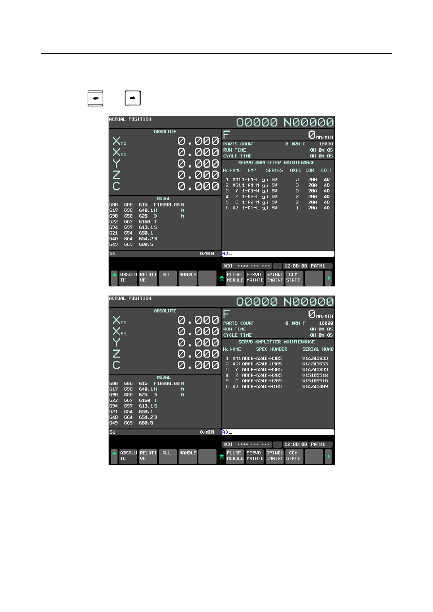
(6)  Servo amplifier maintenance screen 

The servo amplifier maintenance screen displays maintenance information for servo amplifiers. This 

screen consists of the following two pages, either of which can be selected by pressing the cursor 
keys 


  and 


Fig. 1.4.3.1 (g) Servo amplifier maintenance screen 


The servo amplifier maintenance screen displays the following items: 


No........................ Controlled axis number 


NAME ................. Program axis name for each axis 


AMP .................... FSSB line number and  amplifier type of the servo amplifier connected to 

each axis 


SERIES ............... Type and series of the servo amplifier connected to each axis 


(The display of the series name “β

i

SV” is not supported) 


AXES .................. Maximum number of axes controlled by a servo amplifier connected to each 

axis 

B-64693EN-1/01


1. AXIS CONTROL


- 123 - 


CUR. ................... Maximum rating current for servo amplifiers connected to each axis 


EDIT ................... Version number of a servo amplifier connected to each axis 


SPEC NUMBER . Amplifier drawing number of the servo amplifier connected to each axis 


SERIAL NUMB . Serial number of the servo amplifier connected to each axis 


(7)  Spindle amplifier maintenance screen 

The spindle amplifier maintenance screen displays maintenance information for spindle amplifiers. 

This screen consists of the following two pages, either of which can be selected by pressing the 

cursor keys 


  and 


Fig. 1.4.3.1 (h) Spindle amplifier maintenance screen 


The spindle amplifier maintenance screen displays the following items: 


No........................ Spindle number 


NAME ................. Spindle name 

1. AXIS CONTROL


B-64693EN-1/01


- 124 - 


AMP .................... FSSB line number and amplifier type of the spindle amplifier connected to 

each axis 


SERIES ............... Type and series of the spindle amplifier connected to each axis 


AXES .................. Maximum number of axes controlled by a spindle amplifier connected to 

each axis 


PWR. ................... Rated output of the spindle amplifier connected to each axis 


EDIT ................... Version number of a spindle amplifier connected to each axis 


SPEC NUMBER . Amplifier drawing number of the spindle amplifier connected to each axis 


SERIAL NUMB . Serial number of the spindle amplifier connected to each axis 


1.4.3.2 

FSSB automatic setting procedure 

To perform FSSB automatic setting, set items on the FSSB setting screens in (1) to (3) below. 

(1)  Servo amplifier setting screen 


Fig. 1.4.3.2 (a) Servo amplifier setting 


The servo amplifier setting screen displays the following items: 


HRV .................... Current loop 


For this item, enter a value between 2 to 3. 


If a number that falls outside this range is entered, the warning message, “DATA IS OUT OF 

RANGE” appears. 


AXIS ................... Controlled axis number 


For this item, enter a value of between 0 and the maximum number of controlled axes.   


If a number that falls outside this range is entered, the warning message, “DATA IS OUT OF 

RANGE” appears. Setting 0 means that the relevant servo amplifier is not used. 


B-64693EN-1/01


1. AXIS CONTROL


- 125 - 

(2)  Spindle amplifier setting screen 


Fig. 1.4.3.2 (b) Spindle amplifier setting 


The spindle amplifier setting screen displays the following items: 


SP NUM .............. Spindle number 


For this item, enter a value of between 0 and the maximum number of spindles.   


If a number that falls outside this range is entered, the warning message, “DATA IS OUT OF 

RANGE” appears. Setting 0 means that the relevant spindle amplifier is not used. 


(3)  Axis setting screen 


Fig. 1.4.3.2 (c) Axis setting 


On the axis setting screen, the following items can be specified: 


M1 ............. Connector number of the first separate detector interface unit 


M2 ............. Connector number of the second separate detector interface unit 


M3 ............. Connector number of the third separate detector interface unit 


M4 ............. Connector number of the fourth separate detector interface unit 

1. AXIS CONTROL


B-64693EN-1/01


- 126 - 


M5 ............. Connector number of the fifth (first unit for the second FSSB line) separate 

detector interface unit 


M6 ............. Connector number of the sixth separate detector interface unit 


M7 ............. Connector number of the seventh separate detector interface unit 


M8 ............. Connector number of the eighth separate detector interface unit 


For an axis that uses each separate detector interface unit, enter a connector number using a 

number 1 to 8 (maximum number of connectors on a separate detector interface unit). 

When a separate detector interface unit is not used, enter 0. If a number that falls outside this 

range is entered, the warning message, “DATA IS OUT OF RANGE” appears. For a separate 

detector interface unit which is not connected, items are not displayed and values cannot be 

entered. 


Table 1.4.3.2 (a) Connectors and corresponding connector numbers 

Connector 

Connector number 

JF101 

JF102 

JF103 

JF104 

JF105 

JF106 

JF107 

JF108 


CS.............. Cs contour controlled axis 


Enter a spindle number between 1 and the maximum number of spindles for the Cs contour 

controlled axis. When a Cs contour controlled axis is not used, enter 0. If a number that falls 

outside this range is entered, the warning message, “DATA IS OUT OF RANGE” appears. 

When Cs contour control cannot be used, this item is not displayed and any value cannot be 

entered. 


M/S............ Master axis / Slave axis (Slave axis / Dummy axis) 


Enter an odd number for the master axis and an even number for the slave axis for tandem 

control. These numbers must be consecutive and within a range between 1 and the maximum 

number of controlled axes. Enter an odd number for the slave axis and an even number for the 

dummy axis for the electronic gear box (EGB). These numbers must be consecutive and within 

a range between 1 and the maximum number of controlled axes. If a number that falls outside 

this range is entered, the warning message, “DATA IS OUT OF RANGE” appears. For the 

slave and dummy axes for EGB, set bit 0 (SYN) of parameter No. 2011 to 1. When both 

tandem control and electronic gear box cannot be used, this item is not displayed and any value 

cannot be entered. 


On an FSSB setting screen (other than the connection status screen, servo amplifier maintenance screen, 

or spindle amplifier maintenance screen), pressing the soft key [(OPRT)] displays the following soft keys: 


Fig. 1.4.3.2 (d) FSSB automatic setting soft keys 


To enter data, place the machine in the MDI mode or the emergency stop state, position the cursor to a 

desired input item position, then enter desired data and press the soft key [INPUT]. 
(Alternatively, press the 


  key on the MDI unit.) 

When the soft key [SETTING] is pressed after data has been entered, a warning message listed below is 

displayed if the entered data contains an error. When the data is valid, the corresponding FSSB-related 

parameters are set up. To restore the previous value normally set if, for example, an entered value is 

incorrect, press the soft key [CANCEL]. 

When this screen is first displayed after power-on, the previous values set normally are displayed. 

B-64693EN-1/01


1. AXIS CONTROL


- 127 - 


FSSB automatic setting warning messages 

If an invalid setting is detected at FSSB automatic setting, a warning message listed below is displayed. 

EGB dummy axis setting means setting an even number for M/S on the axis setting screen for an axis for 

which bit 0 (SYN) of parameter No. 2011 is set to 1. EGB slave axis setting means setting an odd number 

for M/S on the axis setting screen for an axis for which bit 0 (SYN) of parameter No. 2011 is set to 1. 


Warning message 

Cause 

Cs and M/S are set with the 
same axis 

On the axis setting screen, a value is specified for Cs and M/S for an axis. Do not 
specify any value for Cs and M/S simultaneously. 

Cs and M1-8 are set with the 
same axis 

On the axis setting screen, a value is specified for Cs and 

1-8 for an axis. Do not 

specify any value for Cs and 

1-8 simultaneously. 

Same number is set in AXIS 

On the servo amplifier setting screen, an axis number is set more than once. 
Specify each axis number only once. 

Same number is set in SP 
NUM 

On the spindle amplifier setting screen, a spindle number is set more than once. 
Specify each spindle number only once. 

Same number is set in CS 

On the axis setting screen, a value is set for Cs more than once. Specify each value 
for Cs only once. 

Same number is set in M/S 

On the axis setting screen, a value is set for M/S more than once. Specify each 
value for M/S only once. 

AXIS and Cs are set with the 
same axis 

An axis number for which a value is set for Cs on the axis setting screen is set for 
AXIS on the servo amplifier setting screen. Do not set any axis number for which a 
value is set for Cs, on the servo amplifier setting screen. 

Too many slaves (HRV3) 

The maximum number (15) of slaves per FSSB line for servo HRV3 control is 
exceeded. Reduce the number of slaves connected to an FSSB line to 15 or less. 

Too many slaves (HRV2) 

The maximum number (32) of slaves per FSSB line for servo HRV2 control is 
exceeded. Reduce the number of slaves connected to an FSSB line to 32 or less. 

AXIS is set with EGB dummy 
axis 

An axis number set for EGB dummy axis setting is set for AXIS on the servo 
amplifier setting screen. Do not set any axis number for EGB dummy axis setting, 
on the servo amplifier screen. 

M/S setting is illegal(EGB) 

For M/S, the EGB slave axis setting corresponding to an EGB dummy axis setting 
is not made. Make the EGB slave axis setting. 

AXIS is not set with EGB 
slave axis 

An axis number for EGB slave axis setting is not set for AXIS on the servo amplifier 
setting screen. Set the axis number for EGB slave axis setting, on the servo 
amplifier setting screen. 

AXIS is not set with M/S axis  An axis number set for M/S on the axis setting screen is not set for AXIS on the 

servo amplifier setting screen. Set the axis number for M/S, on the servo amplifier 
setting screen. 

EGB dummy axis setting is 
illegal 

EGB dummy axis setting is made when 32 slaves are connected to the second 
FSSB line. Decrease the number of slaves connected to the second FSSB line. 

M/S setting is illegal 

Invalid M/S setting. Correct the M/S setting. 

Setting is illegal(servo) 

Invalid servo axis setting (servo amplifier setting, axis setting). Correct the servo 
axis setting. 

Setting is illegal(spindle) 

Invalid spindle setting. Correct the spindle setting. 


  CAUTION 

  For the parameters to be specified on the FSSB setting screen, do not attempt to 

directly enter values on the parameter screen using the MDI or a G10 command. 

Use only the FSSB setting screen to enter values for these parameters. 


Examples of FSSB automatic setting 

Examples of FSSB automatic setting for the listed functions are shown below: 


Example 1  Servo HRV2 control (Servo HRV3 control) 


Example 2  Separate detector interface unit 

1. AXIS CONTROL


B-64693EN-1/01


- 128 - 


Example 3  Cs contour control 


Example 4  Tandem control 


Example 5  Electronic gear box 


  -  Example 1    Servo HRV2 control 


X


Y


Z


C


1


X


2


Y


3


Z


4


A


5


B


6


C


CNC


SV(3 axes)


SV: Servo amplifier 

SP: Spindle amplifier


Controlled 

axis 

number


Program 

axis name 

No.1020 

SP


SP


S1


S2


Spindle 

number


1


2


Spindle 

name


S1


S2


SV(2 axes)


First FSSB line 

SV(1 axis)


Fig. 1.4.3.2 (e) Setting example (servo HRV2 control) 


<1>  On the servo amplifier setting screen, enter 2 for HRV and 1, 2, 3, 4, 5, and 6 for AXIS. (To set 

servo HRV3 control, set 3 for HRV.) 


<2>  On the spindle amplifier setting screen, enter 1 and 2 for SP NUM. 

B-64693EN-1/01


1. AXIS CONTROL


- 129 - 


<3>  Press the soft key [SETTING] to perform FSSB automatic setting. 


  -  Example 2  Separate detector interface unit 


X


Y


Z


A


B


C


Axis


1


X


1st JF101


2


Y


2nd JF102


3


Z


2nd JF101


4


A


-


5


B


1st JF102


6


C


2nd JF103


Separate 

detector 

interface unit 

connector 

CNC


SV(2 axes)


M1


SV(2 axes)


M2


SV: Servo amplifier 

SP: Spindle amplifier 

M1/M2: First/second separate detector interface unit 

Controlled 

axis 

number 

Program 

axis name 

No.1020


SP


SP


S1


S2


Spindle 

number


1


2


Spindle 

name


S1


S2


SV(2 axes)


Fig. 1.4.3.2 (f) Setting example (separate detector interface unit) 


Content      ..     19      20      21      22     ..