FANUC Series 0i-MODEL F Plus. CONNECTION MANUAL (FUNCTION) - page 20
1. AXIS CONTROL
B-64693EN-1/01
- 114 -
NOTE
1 Set the following items before executing FSSB automatic setting:
- Set parameter No. 1020 (program axis name for each axis).
- If you use the electronic gear box (EGB) function, set bit 0 (SYN) of parameter
No. 2011 to 1 for the EGB slave axis and EGB dummy axis.
2 There are the following restrictions on FSSB automatic setting:
- The current loop (HRV) is common to all axes.
- Since any servo axis number is not skipped when parameter No. 1023 is set,
the numbers cannot be set so that a specific servo axis number is skipped.
3 FSSB automatic setting cannot be performed when at least one of the following
settings is made:
- The FSSB setting mode is the manual setting 2 mode (bit 0 (FMD) of
parameter No. 1902 is set to 1).
- The serial feedback dummy function is enabled (bit 0 (DMY) of parameter No.
2009 is set to 1).
- A servo axis is disabled for all axes (bit 4 (KSV) of parameter No. 11802 is set
to 1).
- One connector on an separate detector interface unit is used for more than
one axes (bit 5 (SSC) of parameter No. 14476 is set to 1).
- Manual setting 2
After bit 0 (FMD) of parameter No. 1902 is set to 1 or automatic setting has been terminated (bit 1 (ASE)
of parameter No. 1902 is set to 1), manual setting 2 for each parameter for axis setting can be performed.
To perform manual setting 2, set parameters related to FSSB. Refer to the Parameter Manual for the
definition of each parameter.
Example of setting parameters
- When separate detector interface units are connected
X
A
Y
Z
B
C
Axis
1
X
1st JF101
2
Y
2nd JF102
3
Z
2nd JF101
4
A
-
5
B
1st JF102
6
C
2nd JF103
Separate
detector
interface unit
connector
CNC
SV(2 axes)
SV(1 axis)
M1
SV(2 axes)
SV(1 axis)
M2
SV : Servo amplifier
SP : Spindle amplifier
M1/M2 : First/second separate detector
Controlled
axis
number
Program
axis name
No.1020
SP
SP
S1
S2
Spindle
No.3717
1
2
Spindle
number
Spindle
name
S1
S2
1
2
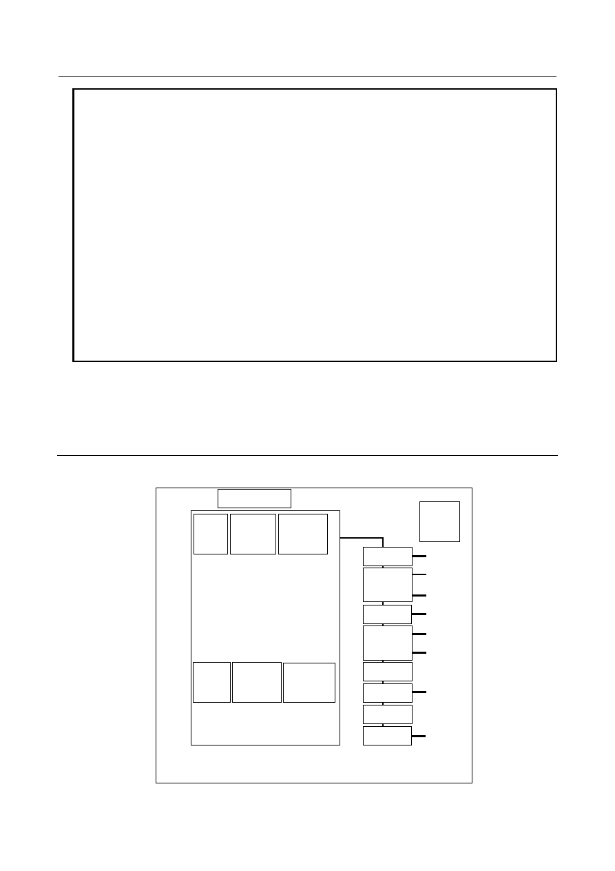
Fig. 1.4.3 (c) Setting example (separate detector interface unit)