FANUC Series 0i-MODEL F Plus. CONNECTION MANUAL (FUNCTION) - page 12
 

  Index      Manuals     FANUC Series 0i-MODEL F Plus. CONNECTION MANUAL (FUNCTION) B-64693EN-1/01


Search            copyright infringement  


Content      ..     10      11      12      13     ..


FANUC Series 0i-MODEL F Plus. CONNECTION MANUAL (FUNCTION) - page 12


1. AXIS CONTROL


B-64693EN-1/01


- 50 - 

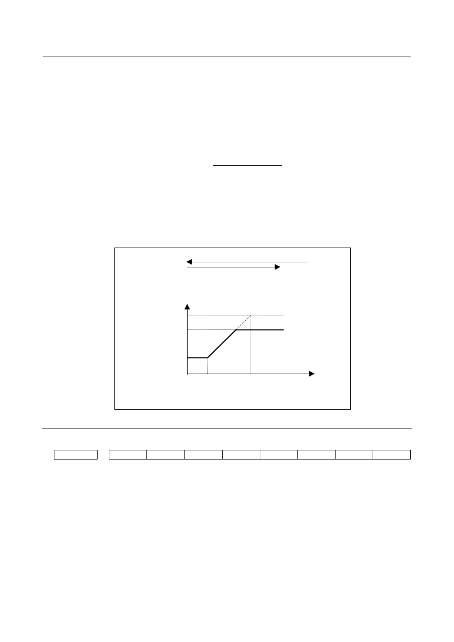
  -  Second stage backlash compensation output 

At the point the tool moves by the distance L1 from the location where the direction of axis moving 

reverses, the second stage backlash compensation output is started. And, at the point the tool moves by 

the distance L2 from the location where the direction of axis moving reverses, the second stage backlash 

compensation output is terminated. The total amount of backlash at the stage where the second stage 

backlash compensation output is terminated, or B2, is the same as the backlash compensation set using 

parameter No.1851. Set the distances L1 and L2, using parameters Nos. 1846 and 1847, respectively. The 

rate of increase of the second stage backlash compensation output is calculated from the following 

equation. 

1

L

2

L

1

B

1851

No.

sec

=

Parameter

ionoutput

hcompensat

ondbacklas

easeof

Rateofincr

   (1) 

If backlash compensation for each rapid traverse and cutting feed is enabled (RBK, bit 4 of parameter No. 

1800 = 1), the total amount of backlash compensation at the stage where the second stage backlash 

compensation output is terminated, or B2, is the backlash compensation as determined by parameters Nos. 

1852 and 1851, the reversed direction, and the rapid traverse/cutting feed mode. The rate of increase of 

the second stage backlash compensation output remains the same as that during cutting. (Expression 1) 

The following shows an example in which the tool is changed from cutting feed to rapid traverse feed and 

the direction reverses. (Fig. 1.3.3 (c)) 


Direction of 

axis moving 

(Direction reverse) 

Total amount of backlash 

compensation after direction reverse 

Distance of travel after 

direction reverse 

(Parameter No. 1851) 

B1 (parameter No. 1848) 

L1 

(parameter No. 

1846) 

L2 

(parameter No. 

1847) 

Cutting feed 

Rapid traverse 

B2 

where B2 = (parameter No. 1851 + parameter No. 1852) / 2 


Fig. 1.3.3 (c) In the case of a change from cutting feed to rapid traverse 


Parameter 


#7 

#6 

#5 

#4 

#3 

#2 

#1 

#0 

1800 


RBK 


[Input type]  Parameter input 


[Data type]  Bit path 


#4  RBK

  Backlash compensation applied separately for cutting feed and rapid traverse 

0:  Not performed 

1:  Performed 


B-64693EN-1/01


1. AXIS CONTROL


- 51 - 


#7 

#6 

#5 

#4 

#3 

#2 

#1 

#0 

1817 


SBL 


[Input type]  Parameter input 


[Data type]  Bit axis 


NOTE 

  When this parameter is set, the power must be turned off before 

operation is continued. 


#2  SBL

  Smooth backlash compensation is : 

0:  Disabled. 

1:  Enabled. 


1846 


Distance for starting the second stage of smooth backlash compensation 


[Input type]  Parameter input 


[Data type]  2-word axis 


[Unit of data]  Detection unit 

[Valid data range]  0 to 999999999 

For each axis, set the distance  from the point where the axis  movement  direction  is 

reversed to the point where the second stage of smooth backlash compensation is started. 


If the following condition is not satisfied, smooth backlash compensation is disabled: 

Value of parameter No. 1846 

 0 

Value of parameter No. 1846 

<

 value of parameter No. 1847 


1847 


Distance for ending the second stage of smooth backlash compensation 


[Input type]  Parameter input 


[Data type]  2-word axis 


[Unit of data]  Detection unit 

[Valid data range]  0 to 999999999 

For each axis, set the distance from the point where the axis  movement  direction  is 

reversed to the point where the second stage of smooth backlash compensation is ended. 


If the following condition is not satisfied, smooth backlash compensation is disabled: 


Value of parameter No. 1846 

 0 

Value of parameter No. 1846 

<

 value of parameter No. 1847 


1848 


Value of the first stage of smooth backlash compensation 


[Input type]  Parameter input 


[Data type]  Word axis 


[Unit of data]  Detection unit 

[Valid data range]  -9999 to 9999 

Set the value of the first stage of smooth backlash compensation for each axis. 

If the setting of this parameter is larger than the total backlash compensation value, 

smooth backlash compensation is not performed. 

When a negative value is set for the backlash compensating value for each axis 

(parameter No. 1851), set a negative value in this parameter. If the sign set in this 

parameter is different from that set for the backlash compensating value for each axis 

(parameter No. 1851), compensation is performed, assuming that the value of the first 

stage of smooth backlash compensation is 0. 


1. AXIS CONTROL


B-64693EN-1/01


- 52 - 

1851 


Backlash compensating value for each axis 


[Input type]  Parameter input 


[Data type]  Word axis 


[Unit of data]  Detection unit 

[Valid data range]  -9999 to 9999 

Set the backlash compensating value for each axis. 

When the machine moves in a direction opposite to the reference position return direction 

after the power is turned on, the first backlash compensation is performed. 


1852 


Backlash compensating value used for rapid traverse for each axis 


[Input type]  Parameter input 


[Data type]  Word axis 


[Unit of data]  Detection unit 

[Valid data range]  -9999 to 9999 

Set the backlash compensating value used in rapid traverse for each axis. (This parameter 

is valid when bit 4 (RBK) of parameter No. 1800 is set to 1.) More precise machining can 

be performed by changing the backlash compensating value depending on the feedrate, 

the cutting feed or the rapid traverse positioning.  Let the measured backlash at cutting 

feed be A and the measured backlash at rapid traverse be B. The backlash compensating 

value is shown below depending on the change of feedrate (cutting feed or rapid traverse) 

and the change of the direction of movement. 


Change of feedrate 

Change of   

direction of movement 

Cutting feed 

to cutting 

feed 

Rapid 

traverse to 

rapid traverse 

Rapid 

traverse to 

cutting feed 

Cutting feed 

to rapid 

traverse 

Same direction 

±a


±

(-

a

Opposite direction 

±

±

±

(B+

a

±

(B+

a


NOTE 

a

=(A-B)/2 

2  The positive or negative direction for compensating values is the 

direction of movement. 


#7 

#6 

#5 

#4 

#3 

#2 

#1 

#0 

11601 


SBN 


[Input type]  Parameter input 


[Data type]  Bit 


#6  SBN

  When the dual  position  feedback  or the monitoring  semi-full  error  is used in servo 

function, the smooth backlash compensation is executed : 

0:  According to the setting of  bit 4 of parameter No.2206 and bit 5 of parameter 

No.2010. 

1:  In the semi-closed loop side. 


B-64693EN-1/01


1. AXIS CONTROL


- 53 - 

1.3.4 

Straightness Compensation 

Overview 

For a machine tool with a long stroke, deviations in straightness between axes may affect the machining 

accuracy. For this reason, when an axis moves, other axes are compensated in detection units to improve 

straightness. This improvement results in better machining accuracy. 

When an axis (parameters Nos. 5711 to 5716) moves, the corresponding compensation axis (parameters 

Nos. 5721 to 5726) is compensated. 

That is, the compensation axis is compensated at the pitch error compensation position (See Subsection 

“Stored Pitch Error Compensation”) of the moving axis.   


Relation between pitch error compensation points and straightness compensation 


1535 

512 

a


b


γ


d


680 

760 

520 

767 

600 


(1) 

(2) 

(3) 

(4) 

602 


Fig. 1.3.4 (a)     


To perform straightness compensation, stored pitch error compensation must be set for the moving axis. 

(1)  Number of the most distant pitch error compensation point on the - side (parameter No.3621) 

(2)  Pitch error compensation point interval (parameter No. 3624) 

(3)  Number of the pitch error compensation point of the reference position (parameter No. 3620) 

(4)  Number of the most distant pitch error compensation point on the + side (parameter No. 3622) 

In Fig. 1.3.4 (a), (1), (3) and (4) are 512, 602 and 767, respectively. 

Straightness compensation parameters must be set. 

a,b,c,d  : Compensation point numbers. (parameters Nos. 5731 to 5754, Nos. 13301 to 13324) 

a

,

b

,

γ

,

d

  : Compensation amounts at compensation points a, b, c and d (parameters Nos. 5761  to 5784, 

Nos. 13351 to 13374) 

In Fig. 1.3.4 (a), a, b, c and d are 520, 600, 680 and 760, respectively. 

Unlike stored pitch error compensation, whose amount is set up for an individual compensation point, an 

amount of straightness compensation is calculated for individual compensation points by setting up four 

typical points and compensation amounts for them. 

Example: 


In above figure, the compensation amount at the individual compensation point is as follows 


At compensation point l between compensation point a and point b: 


a

 + (

b

-

a

) / (b-a) 

×

 (l-a) 


At compensation point m between compensation point b and point c: 


b

 + (

γ

-

b

) / (c-b) 

×

 (m-b) 


At compensation point n between compensation point c and point d: 


γ

 + (

d

-

γ

) / (d-c) 

×

 (n-c) 


1. AXIS CONTROL


B-64693EN-1/01


- 54 - 

Example 

Imagine a table whose Y-axis ball screw is placed on its X-axis ball screw. If the X-axis ball screw is 

inclined at a certain angle because of, for example, bending, the machining precision related to the Y-axis 

becomes low because its ball screw is affected by the gradient of the X-axis ball screw.  (Left figure 

shown Fig. 1.3.4 (b)) 

Specifying the X-axis and Y-axis, respectively, as a moving axis and a compensation axis by means of 

straightness compensation causes the Y-axis (compensation axis) position to be compensated according to 

the X-axis (moving axis) position, thus increasing the machining precision. (Right figure shown Fig. 1.3.4 

(b)) 


Fig. 1.3.4 (b)   


- Function without turning off the power changing parameter of straightness 

compensation value 

The compensation value of straightness compensation on each compensation point (parameter No. 5761 

to 5784, No.13351 to 13374) can be changed without turning off the power by G10, pmc-window or MDI 

input. 

The rewritten data is reflected from the following compensation point. 

This function is activated when bit 0 (RSR) of parameter No.5700 is set to 1. 


NOTE 

1  When all axes have stopped, the parameters of the compensation value can be 

changed.   

2  Please change the data of the interpolated straightness compensation (No.6000 

to 9071 of pitch error setting screen) on the reference point (compensation value 

= 0). 

3  When an illegal value is set to the compensation value parameter in each 

compensation point, the alarm DS5046"ILLEGAL PARAMETER (S-COMP.)" is 

generated. 

At this time, when the movement axis is moved by the manual operation method 

etc, the straightness compensation becomes invalid only the axis that sets an 

illegal value. 


B-64693EN-1/01


1. AXIS CONTROL


- 55 - 

(1) Operation when the compensation value parameter is changed 

When the compensation  value  parameter in each compensation  point  (a to d  point)  of the straightness 

compensation is changed, the changed value is reflected from the next pitch error compensation point. 


Example) 

The compensation point number (parameter No.5731 to 5733) of movement axis 1 is set to "a", "b" and 

"c". And, the value (parameter No.5761 to 5763) of the compensation in each compensation point is set to 

"

a

", "

b

" and "

 γ

". 

When the value "

b

" of the compensation of movement axis 1 is changed to "

b

' " and "

γ

" is changed to "

γ

", the value of the compensation becomes like the solid line of Fig. 1.3.4 (c). 


b


b

Pitch error   

compensation point 

Stroke + of 

moving axis 1 

Change of 

parameter 

Compensation value 

of moving axis 1 

b −> b

γ −> γ

γ

γ


Fig. 1.3.4 (c)    Example 


(2) The value of compensation in reference point 

The compensation value of reference point is outputed based on the setting of the parameter. 


Example) 

The compensation point number (parameter No.5731 to 5733) of movement axis 1 is set to "a", "b" and 

"c". And, the value (paremter No.5761 to 5763) of the compensation in each compensation point is set to 

"

a

", "

b

" and "

 γ

". 

However, the compensation point number "a" is set to be a compensation point number of the reference 

point. At this time, it becomes like the solid line of Fig. 1.3.4 (d). 


1. AXIS CONTROL


B-64693EN-1/01


- 56 - 


a

 point 

= Reference point 

γ


γ 

a


a


b point 

c point 

Compensation of moving axis 1 

Stroke + of 

moving axis 1 

When this function 

is enabled 

When this function 

is invalid 


Fig. 1.3.4 (d)  Example 


NOTE 

  When this function is invalid, the value of the compensation becomes 0 in the 

reference point. (Dotted line of Fig. 1.3.4 (d)) 


Parameter 


#7 

#6 

#5 

#4 

#3 

#2 

#1 

#0 

5700 


RSR 


[Input type]  Parameter input 


[Data type]  Bit path 


#0  RSR

  When the compensation value data (parameter No.5761 to 5784, No.13351 to 13374) of 

the straightness compensation is set, the power off/on is : 

0:  Required. 

1:  Not required. 


NOTE 

1  When this parameter is set, the power must be turned off before 

operation is continued. 

2  When this function is enabled and the compensation value of 

straightness compensation on each compensation point (parameter 

No. 5761 to 5784, No.13351 to 13374) is changed, the alarm of 

turning off the power is not generated. 


5711 


Straightness compensation : Axis number of moving axis 1 


5712 


Straightness compensation : Axis number of moving axis 2 


5713 


Straightness compensation : Axis number of moving axis 3 


5714 


Straightness compensation : Axis number of moving axis 4 


B-64693EN-1/01


1. AXIS CONTROL


- 57 - 

5715 


Straightness compensation : Axis number of moving axis 5 


5716 


Straightness compensation : Axis number of moving axis 6 


NOTE 

  When these parameters are set, the power must be turned off before 

operation is continued. 


[Input type]  Parameter input 


[Data type]  Byte path 

[Valid data range]  1 to Number of controlled axes 

Set the axis number of a moving axis in straight compensation. 

When 0 is set, compensation is not performed. 


5721 


Straightness compensation : Axis number of compensation axis 1 for moving axis 1 


5722 


Straightness compensation : Axis number of compensation axis 2 for moving axis 2 


5723 


Straightness compensation : Axis number of compensation axis 3 for moving axis 3 


5724 


Straightness compensation : Axis number of compensation axis 4 for moving axis 4 


5725 


Straightness compensation : Axis number of compensation axis 5 for moving axis 5 


5726 


Straightness compensation : Axis number of compensation axis 6 for moving axis 6 


NOTE 

  When these parameters are set, the power must be turned off before 

operation is continued. 


[Input type]  Parameter input 


[Data type]  Byte path 

[Valid data range]  1 to Number of controlled axes 


5731 


Straightness compensation : Compensation point number a of moving axis 1 

to 


to 

5734 


Straightness compensation : Compensation point number d of moving axis 1 


5741 


Straightness compensation : Compensation point number a of moving axis 2 

to 


to 

5744 


Straightness compensation : Compensation point number d of moving axis 2 


5751 


Straightness compensation : Compensation point number a of moving axis 3 

to 


to 

5754 


Straightness compensation : Compensation point number d of moving axis 3 


13301 


Straightness compensation : Compensation point number a of moving axis 4 

to 


to 

13304 


Straightness compensation : Compensation point number d of moving axis 4 


13311 


Straightness compensation : Compensation point number a of moving axis 5 

to 


to 

13314 


Straightness compensation : Compensation point number d of moving axis 5 


13321 


Straightness compensation : Compensation point number a of moving axis 6 

to 


to 

13324 


Straightness compensation : Compensation point number d of moving axis 6 


Content      ..     10      11      12      13     ..