FANUC Series 0i-MODEL F Plus. CONNECTION MANUAL (FUNCTION) - page 11
 

  Index      Manuals     FANUC Series 0i-MODEL F Plus. CONNECTION MANUAL (FUNCTION) B-64693EN-1/01


Search            copyright infringement  


Content      ..     9      10      11      12     ..


FANUC Series 0i-MODEL F Plus. CONNECTION MANUAL (FUNCTION) - page 11


1. AXIS CONTROL


B-64693EN-1/01


- 42 - 


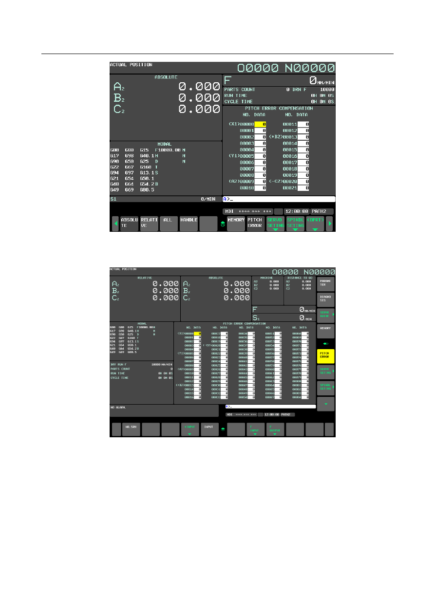
Fig. 1.3.1 (f) PITCH ERROR COMPENSATION screen (10.4-inch display unit) 


3  When the display unit is 15/19-inch, press vertical soft key [PITCH ERROR]. The following screen 

is displayed: 


Fig. 1.3.1 (g) PITCH ERROR COMPENSATION screen (15-inch display unit) 


B-64693EN-1/01


1. AXIS CONTROL


- 43 - 

4  Move the cursor to the compensation point number to be set in either of the following ways: 

Enter the compensation point number and press the soft key [NO.SRH]. 

Move the cursor to the compensation point number using the page keys, 


  and 


, and 

cursor keys, 


, and 


5  Enter a value with numeric keys and press soft key [INPUT]. 


If bit 5 (PAD) of parameter No. 11350 is 1, an axis name is displayed next to the compensation point 

number set in parameter No. 3621 for determining the most negative pitch error compensation point 

number. Also, if the bi-directional pitch error compensation function is enabled, "+ axis name" is 

displayed next to the compensation point number set in parameter No. 3621 for setting the compensation 

point during movement in the positive direction, and "- axis name" is displayed next to the compensation 

point number set in parameter No. 3626 for setting the compensation point during movement in the 

negative direction. 


NOTE 

1  If the setting of the pitch error compensation parameter is not correct, the axis 

name of that axis is not displayed. 

2  For a rotation axis, an axis name is displayed next to the pitch error 

compensation point number of the reference position set in parameter No. 3620. 


Parameter 

3620 


Number of the pitch error compensation position for the reference position for each axis 


NOTE 

  When this parameter is set, the power must be turned off before 

operation is continued. 


[Input type]  Parameter input 


[Data type]  Word axis 

[Valid data range]  0 to 1535 

Set the number of the pitch error compensation position for the reference position for 

each axis. 


3621 


Number of the pitch error compensation position at extremely negative position for each axis 


NOTE 

  When this parameter is set, the power must be turned off before 

operation is continued. 


[Input type]  Parameter input 


[Data type]  Word axis 

[Valid data range]  0 to 1535 

Set the number of the pitch error compensation position at the extremely negative 

position for each axis. 


3622 


Number of the pitch error compensation position at extremely positive position for each axis 


NOTE 

  When this parameter is set, the power must be turned off before 

operation is continued. 


1. AXIS CONTROL


B-64693EN-1/01


- 44 - 


[Input type]  Parameter input 


[Data type]  Word axis 

[Valid data range]  0 to 1535 

Set the number of the pitch error compensation position at the extremely positive position 

for each axis. 

This value must be larger than set value of parameter No.3620. 


3623 


Magnification for pitch error compensation for each axis 


NOTE 

  When this parameter is set, the power must be turned off before 

operation is continued. 


[Input type]  Parameter input 


[Data type]  Byte axis 

[Valid data range]  0 to 100 

Set the magnification for pitch error compensation for each axis. 

If the magnification is set to 1, the same unit as the detection unit is used for the 

compensation data. 

If 0 is set, compensation is not performed. 


3624 


Interval between pitch error compensation positions for each axis 


NOTE 

  When this parameter is set, the power must be turned off before 

operation is continued. 


[Input type]  Parameter input 


[Data type]  Real axis 


[Unit of data]  mm, inch, deg (machine unit) 

[Min. unit of data] Depend on the increment system of the applied axis 

[Valid data range]  See the description below. 

The pitch error compensation positions are arranged with equal spacing. The space 

between two adjacent positions is set for each axis. The minimum interval between pitch 

error compensation positions is limited and obtained from the following equation: 

Minimum interval between pitch error compensation positions = maximum feedrate/7500 

Unit : mm, inch, deg or mm/min, inch/min, deg/min 


[Example]  When the maximum feedrate is 15000 mm/min, the minimum interval between pitch 

error compensation positions is 2 mm. 


3625 


Travel distance per revolution in pitch error compensation of rotary axis type 


NOTE 

  When this parameter is set, the power must be turned off before 

operation is continued. 


[Input type]  Parameter input 


[Data type]  Real axis 


[Unit of data]  mm, inch, deg (machine unit) 

[Min. unit of data] Depend on the increment system of the applied axis 

[Valid data range]  See the description below. 

B-64693EN-1/01


1. AXIS CONTROL


- 45 - 

If the pitch error compensation of rotary axis type is performed (bit 1 (ROSx) of 

parameter No. 1006 is set to 0 and bit 0 (ROTx) of parameter No. 1006 is set to 1), set the 

travel distance per revolution. The travel distance per revolution does not have to be 360 

degrees, and a cycle of pitch error compensation of rotary axis type can be set. 

However, the travel  distance per revolution, compensation interval, and number of 

compensation points must satisfy the following condition: 


(Travel distance per revolution) 

  = (Compensation interval) 

×

 (Number of compensation points) 

The compensation at each compensation point must be set so that the total compensation 

per revolution equals 0. 


NOTE 

  If 0 is set, the travel distance per revolution becomes 360 degrees. 


Warning 

  WARNING 

-  Compensation value range 

  Compensation values can be set within the range from -127 

×

 compensation 

magnification (detection unit) to +127 

×

 compensation magnification (detection 

unit). The compensation magnification can be set for each axis within the range 

from 0 to 100 in parameter 3623. 

-  Pitch error compensation of the rotary axis 

  For the rotating axis, the interval between the pitch error compensation positions 

shall be set to one per integer of the amount of movement (normally 360

°

) per 

rotation. The sum of all pitch error compensation amounts per rotation must be 

made to 0. Also, set the same compensation value to a position and the same 

position with one rotation. 

-  Conditions where pitch error compensation is not performed 

  Note that the pitch error is not compensated in the following cases: 

-  When the machine is not returned to the reference position after turning on the 

power. This excludes the case where an absolute position detector is 

employed. 

-  If the interval between the pitch error compensation positions is 0. 

-  If the compensation position Nos. on the positive or negative direction do not 

fall within the range of 0 to 1535. 

-  For linear axis, if the compensation position Nos. do not conform to the 

following relationship:   

Negative side 

 Reference position < Positive side 


Note 

NOTE 

  For multipath control, axes that have the same axis name but that have different 

paths must use different compensation position Nos. 


Reference item 

Manual name 

Item name 

OPERATOR’S MANUAL (B-64694EN) 

Inputting Pitch Error Compensation Data 
Outputting Pitch Error Compensation Data 


1. AXIS CONTROL


B-64693EN-1/01


- 46 - 

1.3.2 

Backlash Compensation 

Overview 

  -  Backlash compensation 

Function for compensating for lost motion on the machine. Set a compensation value in parameter No. 

1851, in detection units from 0 to 

±

9999 pulses for each axis. 


  -  Backlash compensation for each rapid traverse and cutting feed 

When the bit 4 (RBK) of parameter No.1800 is set to 1, more precise machining can be performed by 

changing the backlash compensating value depending on the feedrate, the rapid traverse or the cutting 

feed. 

Let the measured backlash at cutting feed be A and the measured backlash at rapid traverse be B. The 

backlash compensating value is shown Table 1.3.2 (a) depending on the change of feedrate (cutting feed 

or rapid traverse) and the change of the direction of movement. 

Table 1.3.2 (a) 

Change of feedrate 

Change of   

direction of movement 

Cutting feed to 

cutting feed 

Rapid traverse 

to rapid traverse 

Rapid traverse 

to cutting feed 

Cutting feed to 

rapid traverse 

Same direction 

±a


±

(-

a

Opposite direction 

±

±

±

(B+

a

±

(B+

a


a

= (A-B) / 2 (However, if 

a

 is not an integer, it is 

a

= (A-(B-1)) / 2.) 

The positive or negative direction for compensating values is the direction of movement. 


Fig. 1.3.2 (a) 


Assign the measured backlash at cutting feed (A) in parameter No. 1851 and that at rapid traverse 

(B) in parameter No. 1852. 


- Tolerance for reverse pulse of the axis moving direction 

The output of the backlash compensation pulse is controlled, from reversing of the movement direction of 

the axis to multiplying the movement value (unit of detection) that set by the parameter (No.1853). 

As a result, the output of the backlash compensation pulse to the movement minutely repeated can be 

controlled. 

And, the tolerance parameter (No.1853) for reverse pulse of the axis moving direction is also effective in 

the following functions. 

- Backlash compensation for each rapid traverse and cutting feed 

  (Backlash of the same direction is excluded) 

- Smooth backlash compensation 

B-64693EN-1/01


1. AXIS CONTROL


- 47 - 


Fig. 1.3.2 (b) Tolerance for reverse pulse of the axis moving direction 


NOTE 

  When an excessive value is input to the parameter (No.1853) of this function, the 

backlash compensation for each rapid traverse and cutting feed output of the same 

direction is done. 

When the backlash must be invalided, please adjust compensation value 

parameter (No.1848,1851,1852) to 0. 


Parameter 


#7 

#6 

#5 

#4 

#3 

#2 

#1 

#0 

1800 


RBK 


[Input type]  Parameter input 


[Data type]  Bit path 


#4  RBK

  Backlash compensation applied separately for rapid traverse and cutting feed 

0:  Not performed 

1:  Performed 


#7 

#6 

#5 

#4 

#3 

#2 

#1 

#0 

1802 


BKL15x 


[Input type]  Parameter input 


[Data type]  Bit axis 


#4  BKL15x

  When the direction of a movement is determined in backlash compensation: 

0:  The compensation amount is not considered. 

1:  The compensation amount (pitch error, straightness, external machine coordinate   


system shift, etc.) is considered. 


1851 


Backlash compensating value for each axis 


[Input type]  Parameter input 


[Data type]  Word axis 


[Unit of data]  Detection unit 

[Valid data range]  -9999 to 9999 

Set the backlash compensating value for each axis. 

Movement direction 

of axis


(direction reverse)


Total value of backlash compensation 

after direction reverses 

Value of movement 

after direction reverses 

0


Parameter 

(No.1851)


Disable bandwidth L0 

Parameter (No.1853)


1. AXIS CONTROL


B-64693EN-1/01


- 48 - 

When the machine moves in a direction opposite to the reference position return direction 

after the power is turned on, the first backlash compensation is performed. 


1852 


Backlash compensating value used for rapid traverse for each axis 


[Input type]  Parameter input 


[Data type]  Word axis 


[Unit of data]  Detection unit 

[Valid data range]  -9999 to 9999 

Set the backlash compensating value used in rapid traverse for each axis. (This parameter 

is valid when bit 4 (RBK) of parameter No. 1800 is set to 1.) More precise machining can 

be performed by changing the backlash compensating value depending on the feedrate, 

the cutting feed or the rapid traverse positioning. Let the measured backlash at cutting 

feed be A and the measured backlash at rapid traverse be B. The backlash compensating 

value is shown Table 1.3.2 (b) depending on the change of feedrate (cutting feed or rapid 

traverse) and the change of the direction of movement. 


Table 1.3.2 (b) 

Change of feedrate 

Change of   

direction of movement 

Cutting feed 

to cutting 

feed 

Rapid 

traverse to 

rapid traverse 

Rapid 

traverse to 

cutting feed 

Cutting feed 

to rapid 

traverse 

Same direction 

±a


±

(-

a

Opposite direction 

±

±

±

(B+

a

±

(B+

a


NOTE 

a

=(A-B)/2 (However, if 

a

 is not an integer, it is 

a

= (A-(B-1)) / 2.) 

2  The positive or negative direction for compensating values is the 

direction of movement. 


1853 


Tolerance for reverse pulse of axis moving direction of backlash compensation 


[Input type]  Parameter input 


[Data type]  2-word axis 


[Unit of data]  Detection unit 

[Valid data range]  0 to 999999999 

The tolerance value  for reverse  pulse of the axis moving direction  of the backlash 

compensation is set. 

After the value set by the parameter at time when the direction of the movement changed 

is moved, the backlash compensation pulse is output. 

When this parameter set to 0, the function of invalid bandwidth is disabled, and the 

backlash compensation is done when the direction of the movement is changed. 


Caution 

  CAUTION 

  The backlash compensation for each rapid traverse and cutting feed is not 

performed until the first reference position return is completed after the power is 

turned on. Under this state, the normal backlash compensation is performed 

according to the value specified in parameter No. 1851 irrespective of a rapid 

traverse or a cutting feed. 


B-64693EN-1/01


1. AXIS CONTROL


- 49 - 

Note 

NOTE 

1  When backlash compensation is applied separately for cutting feed and rapid 

traverse, jog feed is regarded as cutting feed. 

2  If parameter No.1851 is changed when the backlash compensation or the 

backlash compensation for each rapid traverse and cutting feed is performed; 

the new compensation value becomes valid when the machine moves in a 

direction opposite to the reference return direction. 

3  If parameter No.1852 is changed when the backlash compensation for each rapid 

traverse and cutting feed is performed; 

the new compensation value becomes valid when the machine moves at rapid 

traverse regardless of direction. 


1.3.3 

Smooth Backlash 

Explanation 

With normal backlash compensation, all backlash compensating value are output at the location where the 

direction of axis moving reverses. (Fig. 1.3.3 (a)) 


Direction of 

axis moving 

(Direction reverse) 

Total amount of backlash compensation after direction reverse 

Distance of travel after 

direction reverse 

Parameter No. 1851 


Fig. 1.3.3 (a) Normal backlash compensation 


With smooth backlash compensation, backlash compensating value are output in accordance with the 

distance from the location where the direction of axis moving reverses, so that fine backlash 

compensation corresponding to the characteristics of the machine is possible. (Fig. 1.3.3 (b)) 


Direction of 

axial moving 

(Direction reverse) 

Total amount of backlash compensation 

after direction reverse 

Distance of travel after 

direction reverse 

B2 (parameter No. 1851) 

B1 (parameter No. 1848) 

L1 

(parameter No. 1846) 

L2 

(parameter No. 1847) 


Fig. 1.3.3 (b) Smooth backlash compensation 


To enable this function set SBL, bit 2 of parameter No. 1817, to 1. 


  -  First stage backlash compensation output 

At the location where the direction of axis moving reverses, the first stage backlash compensation output 

is performed. Set the first stage backlash compensation B

1

, using parameter No.1848. 


Content      ..     9      10      11      12     ..