FANUC Series 0i-MODEL F Plus. CONNECTION MANUAL (FUNCTION) - page 9
 

  Index      Manuals     FANUC Series 0i-MODEL F Plus. CONNECTION MANUAL (FUNCTION) B-64693EN-1/01


Search            copyright infringement  


Content      ..     7      8      9      10     ..


FANUC Series 0i-MODEL F Plus. CONNECTION MANUAL (FUNCTION) - page 9


1. AXIS CONTROL


B-64693EN-1/01


- 26 - 

Caution 

  CAUTION 

1  In general, interlock is applied to an axis while the servo off signal for that axis is 

“1”. 

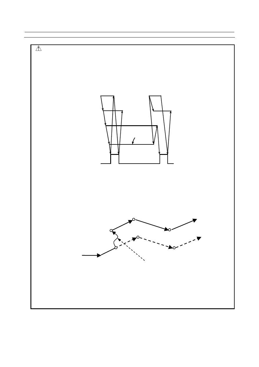
2  The mechanical clamp is done by using the auxiliary function. Set the timing for 

the auxiliary function, mechanical clamp and servo off signals as shown in the 

Fig. 1.2.8 (a). The clamp command auxiliary function should be executed only 

after the distribution end signal DEN <Fn001.3> turned to “1”. 


MF


Machine 

clamp 

SVF1


FIN


Servo off state


Clamp command


Unclamp command


DEN


Fig. 1.2.8 (a) 

3  If, during automatic operation, a servo off signal is issued with the setting that 

causes follow-up to be performed (a bit 0 (FUPx) of parameter No.1819 = 0 and a 

follow-up signal *FLWU<Gn007.5> = “0”), even if the machine is moved with 

external force or other means, the travel distance will not immediately reflected in 

the program coordinate system. Until it is reflected, the machine path will be 

shifted by the amount of movement due to the external force as in the Fig. 1.2.8 

(b). 


Programmed machine path 

Servo off 

Servo on 

Actual machine path 

During servo off, movement due to external force 


Fig. 1.2.8 (b) 

  The following method is available to reflect the amount of movement during servo 

off in the program coordinate system. If not wishing to shift the path, be sure to 

follow the procedure below to adjust the coordinates and execute an absolute 

command. 

-  Exit from automatic operation with a reset, single block stop, or feed hold, and 

then make a restart. 

B-64693EN-1/01


1. AXIS CONTROL


- 27 - 

  CAUTION 

4  If a servo off signal is issued with the setting that does not cause follow-up to be 

performed (a bit 0 (FUPx) of parameter No.1819 = 1 or a follow-up signal 

*FLWU<Gn007.5> = “1”), even if the machine is moved with external force or 

other means, the machine will be retracted by the travel distance in the servo on 

state and, therefore, the path will never shift in subsequent automatic operation. 

The amount of movement due to the external force in the servo off state is 

regarded as a servo positional deviation and is stored inside the CNC. Thus, 

when a servo on signal is issued, axis moving occurs to cancel this servo 

positional deviation. The machine moves at a speed in accordance with the servo 

loop gain and if the amount is large, this may give the machine a shock. 

5  If the positioning deviation exceeds the value set in the parameter No.1830 in 

servo-off state, alarm SV0410, “EXCESS ERROR (STOP)” is occurred. If the 

parameter No.1830 is set to 0, the positioning deviation is not checked in 

servo-off state. 


Parameter 

1830 


Axis-by-axis positional deviation limit at servo-off time 


[Input type]  Parameter input 


[Data type]  2-word axis 


[Unit of data]  Detection unit 

[Valid data range]  0 to 99999999 

This parameter is used to set a positional deviation limit at servo-off time, on an 

axis-by-axis basis. 

If the value specified with this parameter is exceeded at servo-off time, a servo alarm is 

issued to cause an immediate stop (same as an emergency stop). Usually, set the same 

value as a positional deviation limit at stop time. 


NOTE 

  If this parameter is set to 0, the positioning deviation is not checked in 

servo-off state. 


Reference item 

Manual name 

Item name 

CONNECTION MANUAL (FUNCTION) 

(

this manual

)


Follow-up 


1.2.9 

Position Switch 

Overview 

Position switch signals can be output to the PMC while the machine coordinates along a controlled axes 

are within a specified ranges. 

Using parameters, specify arbitrary controlled axes and machine coordinate operating ranges for which 

position switch signals PSW01 to PSW16 <Fn070,Fn071> are output. 

Up to 10 position switch signals can be output. 

Up to 16 points can be expanded by setting bit 1 (EPW) of parameter No. 6901 to 1. 


  CAUTION 

  The position switch function is enabled after reference position return is 

completed. 

1. AXIS CONTROL


B-64693EN-1/01


- 28 - 


Signal 

Position switch signals PSW01 to PSW16<Fn070, Fn071> 

  [Classification]  Output signal 


[Function]  Indicates that the machine coordinates along the controlled axes specified by parameters 

Nos. 6910 to 6925 are within the ranges specified by parameters Nos. 6930 to 6945 and 

6950 to 6965. 

The position switch signal corresponding to the n-th position switch 

function is PSWn.   

(n : 1 to 16) 

  [Output cond.]  These signals are “1” in the following case: 

When the machine coordinates along the controlled axes are within the specified 

ranges. 

These signals are “0” in the following case: 

When the machine coordinates along the controlled axes are not within the specified 

ranges. 


Signal address 


#7 

#6 

#5 

#4 

#3 

#2 

#1 

#0 

Fn070 


PSW08 

PSW07 

PSW06 

PSW05 

PSW04 

PSW03 

PSW02 

PSW01 


Fn071 


PSW16 

PSW15 

PSW14 

PSW13 

PSW12 

PSW11 

PSW10 

PSW09 


Parameter 


#7 

#6 

#5 

#4 

#3 

#2 

#1 

#0 

6901 


PSA 

EPW 


[Input type]  Parameter input 


[Data type]  Bit path 


#1  EPW

  The number of position switches is: 

0:  Not extended. 

1:  Extended. 


#2  PSA

  In determination of a position switch function operation range, a servo delay amount 

(positional deviation) and a delay amount in acceleration/deceleration control are: 

0:  Not considered. 

1:  Considered. 


6910 


Controlled axis for which the 1-st position switch function is performed (PSWA01) 

to 


to 

6925 


Controlled axis for which the 16-th position switch function is performed (PSWA16) 


[Input type]  Parameter input 


[Data type]  Byte path 

[Valid data range]  0 to Number of controlled axes 

Set the controlled axis number (intra-path relative axis number) corresponding to one of 

the first to sixteenth position switch functions. When the machine coordinate of the 

corresponding axis is within a parameter-set range, the corresponding position switch 

signal is output to the PMC. 


B-64693EN-1/01


1. AXIS CONTROL


- 29 - 

NOTE 

  The setting of 0 means that the position switch function of the 

number is not used. 


6930 


Maximum value of the operating range of the 1-st position switch (PSW101) 

to 


to 

6945 


Maximum value of the operating range of the 16-th position switch (PSW116) 


[Input type]  Parameter input 


[Data type]  Real path 


[Unit of data]  mm, inch, deg (machine unit) 

[Min. unit of data] Depend on the increment system of the reference axis 

[Valid data range]  9 digit of minimum unit of data (refer to standard parameter setting table (A)) 

(When the increment system is IS-B, -999999.999 to +999999.999) 

Set the maximum value of the operating range of the first to sixteenth position switches. 


NOTE 

1  For a diameter-specified axis, use diameter values to specify the 

parameters used to set the maximum and minimum values of an 

operating range. 

2  The position switch function is enabled upon completion of 

reference position return. 

3  Please do not specify the range that steps over 360° for the rotation 

axis. 


6950 


Minimum value of the operating range of the 1-st position switch (PSW201) 

to 


to 

6965 


Minimum value of the operating range of the 16-th position switch (PSW216) 


[Input type]  Parameter input 


[Data type]  Real path 


[Unit of data]  mm, inch, deg (machine unit) 

[Min. unit of data] Depend on the increment system of the reference axis 

[Valid data range]  9 digit of minimum unit of data (refer to standard parameter setting table (A)) 

(When the increment system is IS-B, -999999.999 to +999999.999) 

Set the minimum value of the operating range of the first to sixteenth position switches. 


NOTE 

1  For a diameter-specified axis, use diameter values to specify the 

parameters used to set the maximum and minimum values of an 

operating range. 

2  The position switch function is enabled upon completion of 

reference position return. 

3  Please do not specify the range that steps over 360° for the rotation 

axis. 


1.2.10 

High-Speed Position Switch 

Overview 

The high-speed position switch function monitors the current position at shorter intervals than the normal 

position switch function to output a high-speed precise position switch signal. 

1. AXIS CONTROL


B-64693EN-1/01


- 30 - 

In the same way as for the normal position switch function, using parameters, specify arbitrary controlled 

axes and machine coordinate operating ranges for which position switch signals are output. 

Up to six high-speed position signals can be output. Up to 16 points can be expanded by setting bit 7 

(HPE) of parameter No. 8500 to 1. 


  CAUTION 

  The high-speed position switch function is enabled after reference position return 

is completed. 


Explanation 

  -  Output addresses of high-speed position switch signals 

High-speed position switch signals are output to the PMC Y signal addresses set using parameter No. 

8565. If a nonexistent address is set for the parameter, the high-speed position switch function is disabled. 

If you do not want to use the PMC Y signal addresses, you can set bit 0 (HPF) of parameter No. 8501 to 1 

to use high-speed position switch signals as normal output signals (using F signal addresses). 


  WARNING 

  Never use the Y signal used on the PMC ladder. In case of using it with mistakes, 

the machine may perform unexpected operation. 


Signal 

High-speed position switch signals HPS01 to HPS16<Yxxx,Yxxx

+1

><Fn293,Fn294> 

  [Classification]  Output signal 


[Function]  Indicates that the machine coordinates along the controlled axes specified by parameters 

Nos. 8570 to 8579 and 12201 to 12206 are within the ranges specified by parameters Nos. 

8580 to 8589, 12221 to 12226, 8590 to 8599, and 12241 to 12246. 

The position switch signal corresponding to the n-th position switch function is HPSn. 

(n : 1 to 16) 

  [Output cond.]  These signals are “1” in the following case: 

When the machine coordinate value along the controlled axis is within a specified 


range. 

These signals are “0” in the following case: 

When the machine coordinate value the along the controlled axis is not within a 


specified range. 


Signal address 


#7 

#6 

#5 

#4 

#3 

#2 

#1 

#0 

Yxxx 


HPS08 

HPS07 

HPS06 

HPS05 

HPS04 

HPS03 

HPS02 

HPS01 


Yxxx+1 


HPS16 

HPS15 

HPS14 

HPS13 

HPS12 

HPS11 

HPS10 

HPS09 

xxx indicates the address set using parameter No. 8565. 

When bit 0 (HPF) of parameter No. 8501 is set to 1, the signal addresses are F293 and F294. (Y signal 

addresses are not used.) 


Parameter 


#7 

#6 

#5 

#4 

#3 

#2 

#1 

#0 

8500 


HPE 


[Input type]  Parameter input 


[Data type]  Bit path 


#7  HPE

  The maximum number of high-speed position switches is: 

0:  6. 

B-64693EN-1/01


1. AXIS CONTROL


- 31 - 

1:  16. 


#7 

#6 

#5 

#4 

#3 

#2 

#1 

#0 

8501 


HPS 

HPF 


[Input type]  Parameter input 


[Data type]  Bit path 


NOTE 

  When at least one of these parameters is set, the power must be 

turned off before operation is continued. 


#0  HPF

  The output signal of a high-speed position switch is output to: 

0:  Address Y. 

1:  Address F. 


#1  HPS

  The current position used with the high-speed position switch: 

0:  Considers a servo error. 

1:  Does not consider a servo error. 


#7 

#6 

#5 

#4 

#3 

#2 

#1 

#0 

8504 


E08 

E07 

E06 

E05 

E04 

E03 

E02 

E01 


8505 


E16 

E15 

E14 

E13 

E12 

E11 

E10 

E09 


[Input type]  Parameter input 


[Data type]  Bit path 


   E01 to E16

    These parameters specify whether to enable or disable each corresponding high-speed 

position switch. 

The Table 1.2.10 (a) shows the correspondence between the bits and switches. 

The settings of each bit have the following meaning: 

0:  The switch corresponding to the bit is enabled. 

1:  The switch corresponding to the bit is disabled (always outputs 0). 


Table 1.2.10 (a) 

Parameter 

Switch 

E01 

1st high-speed position switch 

E02 

2nd high-speed position switch 

E03 

3rd high-speed position switch 

E16 

16th high-speed position switch 


8565 


Output address of the high-speed position switch signal 


NOTE 

  When this parameter is set, the power must be turned off before 

operation is continued. 


1. AXIS CONTROL


B-64693EN-1/01


- 32 - 


[Input type]  Parameter input 


[Data type]  Word path 

[Valid data range]  0 to 126 

This parameter sets a Y signal address to which the high-speed position switch signal is 

output. The Y signal addresses consisting of the value set in this parameter and the set 

value plus 1 are used. 

If a nonexistent address is set, the high-speed position switch function is disabled. When 

bit 0 (HPF) of parameter No. 8501 is set to 1, however, this parameter has no effect. 


Table 1.2.10 (b) Relationship between the high-speed position switches and the addresses to 

be output 


Signal address to 

be output 

Controlled axes 

number 

Maximum 

operation range 

Minimum 

operation range 

1st to 8th 

“Value set in the 
parameter 
No.8565” 

8570 to 8577 

8580 to 8587 

8590 to 8597 

9th to 16th 

“Value set in the 
parameter 
No.8565” + 1 

8578 to 8579, 
12201 to 12206 

8588 to 8589, 
12221 to 12226 

8598 to 8599, 
12241 to 12246 


  WARNING 

1  Be sure not to use any Y signal already used in the PMC ladder with 

this function. If used, the machine may behave in an unexpected 

manner. 

2  If you want to use high-speed position switches for multiple paths, 

use a different Y signal output address for each path. 


  CAUTION 

1  Specifying a nonexistent signal address causes the high-speed 

position switch function to be disabled. 

2  Y signal address Y127 cannot be specified for this function. 

3  Address output signals (Y1001 and above) on the M-NET board 

cannot be specified for this function. 

4  When "0" is set to the parameter, it is output to Y0 and Y1. Please 

set the available address when the high-speed position switch is 

used. 


8570 


Controlled axis for which the first high-speed position switch function is performed 

to 


to 

8579 


Controlled axis for which the tenth high-speed position switch function is performed 


12201 


Controlled axis for which the eleventh high-speed position switch function is performed 

to 


to 

12206 


Controlled axis for which the sixteenth high-speed position switch function is performed 


[Input type]  Parameter input 


[Data type]  Byte path 

[Valid data range]  1 to number of controlled axes 

Each of these parameters sets a controlled axis number for which each of the first  to 

sixteenth high-speed position switch functions is performed.   

Set 0 for the number corresponding to a high-speed position switch which is not to be 

used. 


B-64693EN-1/01


1. AXIS CONTROL


- 33 - 

NOTE 

  Parameters Nos. 8576 to 8579 and 12201 to 12206 are valid only 

when bit 7 (HPE) of parameter No. 8500 is 1. 


8580 


Maximum value of the operation range of the first high-speed position switch 

to 


to 

8589 


Maximum value of the operation range of the tenth high-speed position switch 


12221 


Maximum value of the operation range of the eleventh high-speed position switch 

to 


to 

12226 


Maximum value of the operation range of the sixteenth high-speed position switch 


[Input type]  Parameter input 


[Data type]  Real path 


[Unit of data]  mm, inch, deg (machine unit) 

[Min. unit of data] Depend on the increment system of the reference axis 

[Valid data range]  9 digit of minimum unit of data (refer to standard parameter setting table (A)) 

(When the increment system is IS-B, -999999.999 to +999999.999) 

Each of these parameters sets the maximum value of the operation range of each of the 

first to sixteenth high-speed position switches. If such a setting that maximum value < 

minimum value is made, no operation range exists, so that the high-speed position switch 

does not operate. 


NOTE 

  Parameters Nos. 8586 to 8589 and 12221 to 12226 are valid only 

when bit 7 (HPE) of parameter No. 8500 is 1. 


8590 


Minimum value of the operation range of the first high-speed position switch 

to 


to 

8599 


Minimum value of the operation range of the tenth high-speed position switch 


12241 


Minimum value of the operation range of the eleventh high-speed position switch 

to 


to 

12246 


Minimum value of the operation range of the sixteenth high-speed position switch 


[Input type]  Parameter input 


[Data type]  Real path 


[Unit of data]  mm, inch, deg (machine unit) 

[Min. unit of data] Depend on the increment system of the reference axis 

[Valid data range]  9 digit of minimum unit of data (refer to standard parameter setting table (A)) 

(When the increment system is IS-B, -999999.999 to +999999.999) 

Each of these parameters sets the minimum value of the operation range of each of the 

first to sixteenth high-speed position switches. If such a setting that maximum value < 

minimum value is made, no operation range exists, so that the high-speed position switch 

does not operate. 


NOTE 

  Parameters Nos. 8596 to 8599 and 12241 to 12246 are valid only 

when bit 7 (HPE) of parameter No. 8500 is 1. 


Content      ..     7      8      9      10     ..